


Chapter 7. Locating connectors, controls and components
This section provides illustrations to help locate the various connectors, controls and components of the
computer.
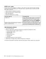
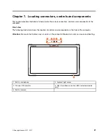
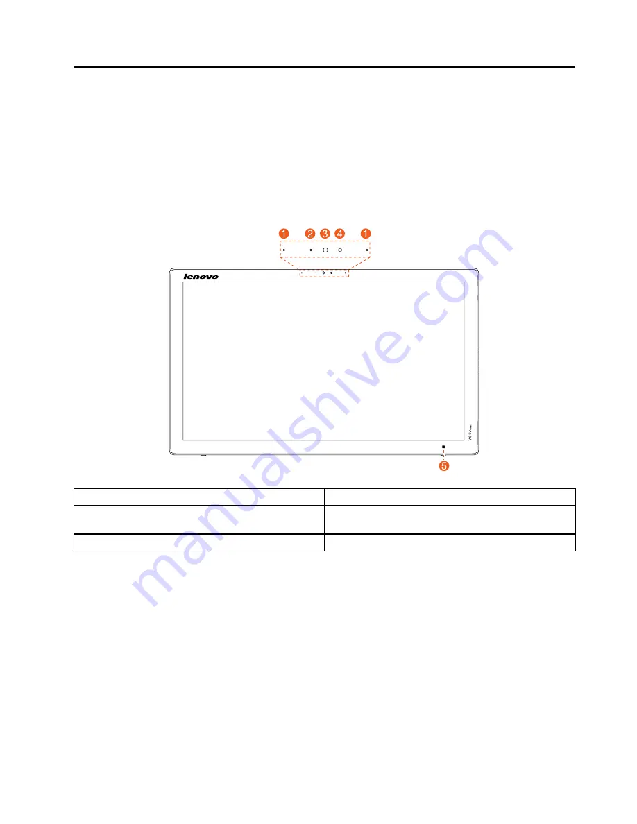
Front view
The following illustration shows the location of controls and components on the front of the computer.
Attention:
Be careful not to block any air vents on the computer. Blocked air vents can cause overheating.
1. Built-in microphone
4. Ambient light sensor
2. Camera LED indicator
5. Near Field Communication (NFC) (selected models
only)
3. Built-in camera
© Copyright Lenovo 2015, 2015
21
Summary of Contents for YOGA HOME 500
Page 2: ......
Page 6: ...iv YOGA HOME 500 All In One PC Hardware Maintenance Manual ...
Page 8: ...2 YOGA HOME 500 All In One PC Hardware Maintenance Manual ...
Page 16: ...10 YOGA HOME 500 All In One PC Hardware Maintenance Manual ...
Page 18: ...12 YOGA HOME 500 All In One PC Hardware Maintenance Manual ...
Page 24: ...18 YOGA HOME 500 All In One PC Hardware Maintenance Manual ...
Page 30: ...24 YOGA HOME 500 All In One PC Hardware Maintenance Manual ...
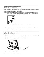
Page 33: ...a Connect the new power adapter to the same connector Chapter 8 Replacing hardware 27 ...
Page 50: ...44 YOGA HOME 500 All In One PC Hardware Maintenance Manual ...
Page 56: ...50 YOGA HOME 500 All In One PC Hardware Maintenance Manual ...