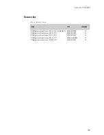


Lenovo YT3-850
33
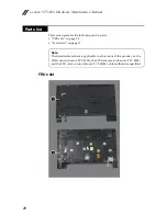
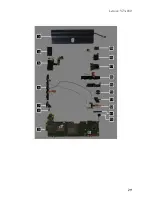
This section presents exploded figures with the instructions to indicate how to
remove and replace the FRU. Make sure to observe the following general rules:
1.
Do not attempt to service any computer unless you have been trained and
certified. An untrained person runs the risk of damaging parts.
2.
Before replacing any FRU, review “FRU replacement notices” on page 32.
3.
Begin by removing any FRUs that have to be removed before the failing FRU.
Any of such FRUs are listed at the top of the section that describes the
detailed removing and replacing procedure for the failing FRU. Remove
them in the order in which they are listed.
4.
Follow the correct sequence in the steps to remove the FRU, while referring
to figures provided in the procedure.
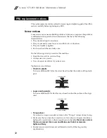
5.
When turning a screw to replace an FRU, turn it in the direction as given by
the arrow in the figure.
6.
When removing the FRU, move it in the direction as given by the arrow in the
figure.
7.
To put the new FRU in place, reverse the removal procedures and follow any
of the notes that pertain to replacement. For information about connecting
and arranging internal cables, see “Components location” on page 26.
8.
When replacing an FRU, use the correct screw as specified in the procedures.
Attention:
After replacing an FRU, do not turn on the computer until you have
made sure that all screws, springs, and other small parts are in place and none
are loose inside the computer. Verify this by shaking the computer gently and
listening for rattling sounds. Metallic parts or metal flakes can cause electrical
short circuits.
Attention:
The system board is sensitive to, and can be damaged by, electrostatic
discharge. Before touching it, establish personal grounding by touching a
ground point with one hand or using an electrostatic discharge (ESD) strap
(P/N 6405959) to remove potential shock reasons.
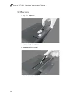
Removing and replacing an FRU
DANGER
Before removing any FRU, turn off the computer, unplug all power cords
from electrical outlets, remove the battery pack, and then disconnect any of
the interconnecting cables.
Summary of Contents for YOGA Tab 3 YT3-850F
Page 1: ...YOGA Tab 3 8 Hardware Maintenance Manual Lenovo YT3 850F Lenovo YT3 850L Lenovo YT3 850M ...
Page 33: ...Lenovo YT3 850 29 ...
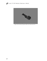
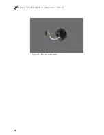
Page 52: ...Lenovo YT3 850 Hardware Maintenance Manual 48 Figure 3 10 The removed rotated camera ...
Page 69: ...Lenovo YT3 850 65 Figure 8 3 The removed vibrator motor ...
Page 77: ...Lenovo YT3 850 73 Figure 10 6 The removed USB and volume key FPC ...
Page 79: ...Lenovo YT3 850 75 Figure 11 3 The removed volume key ...
Page 84: ...Lenovo YT3 850 Hardware Maintenance Manual 80 Figure 13 6 The removed antenna ...
Page 88: ...Lenovo YT3 850 Hardware Maintenance Manual 84 Figure 15 5 The removed antenna ...


