background image

Lenovo 1371 Hardware Maintenance Manual

6

Any computer part containing transistors or integrated circuits (ICs) should be 
considered sensitive to electrostatic discharge (ESD). ESD damage can occur 
when there is a difference in charge between objects. Protect against ESD damage 
by equalizing the charge so that the machine, the part, the work mat, and the 
person handling the part are all at the same charge.

When handling ESD-sensitive parts:
• Keep the parts in protective packages until they are inserted into the product.
• Avoid contact with other people.
• Wear a grounded wrist strap against your skin to eliminate static on your 

body.

• Prevent the part from touching your clothing. Most clothing is insulative and 

retains a charge even when you are wearing a wrist strap.

• Use the black side of a grounded work mat to provide a static-free work 

surface. The mat is especially useful when handling ESD-sensitive devices.

• Select a grounding system, such as those listed below, to provide protection 

that meets the specific service requirement.

Attach the ESD ground clip to any frame ground, ground braid, or green-
wire ground.

When working on a double-insulated or battery-operated system, use an 
ESD common ground or reference point. You can use coax or connector-
outside shells on these systems.

Use the round ground prong of the ac plug on ac-operated computers.

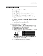
Electrical grounding of the computer is required for operator safety and correct 
system function. Proper grounding of the electrical outlet can be verified by a 
certified electrician.

Handling devices that are sensitive to electrostatic discharge

Notes:

1.

Use product-specific ESD procedures when they exceed the 
requirements noted here.

2.

Make sure that the ESD protective devices you use have been certified 
(ISO 9000) as fully effective.

Notes:

The use of a grounding system to guard against ESD damage is desirable but 
not necessary.

Grounding requirements

Summary of Contents for YOGA Tablet 2-1371F

Page 1: ...YOGA TABLET 2 with Windows Hardware Maintenance Manual YOGA Tablet 2 1371F ...

Page 2: ...eveloped exclusively at private expense and are sold to governmental entities as commercial items as defined by 48 C F R 2 101 with limited and restricted rights to use reproduction and disclosure LIMITED AND RESTRICTED RIGHTS NOTICE If products data computer software or services are delivered pursuant to a General Services Administration GSA contract use reproduction or disclo sure is subject to ...

Page 3: ...ted service information 23 Security 23 Power management 23 Activating Deactivating the Display 23 Lenovo 1371 24 Specifications 24 FRU replacement notices 26 Screw notices 26 Removing and replacing an FRU 27 1010 Rear cover 28 1020 Battery pack 32 1030 HDMI and audio jack FPC 43 1040 Right speaker 46 1050 Subwoofer speaker with microphone FPC 48 1060 Hinge frame latch 51 1070 Main FPC 53 1080 Main...

Page 4: ... product specific section includes service reference and product specific parts information About this manual Note The information provided in this manual is applicable to both product versions mentioned above unless otherwise specified Important This manual is intended only for trained servicers who are familiar with Lenovo products Use this manual to troubleshoot problems effectively Before serv...

Page 5: ...ervice a Lenovo computer General safety on page 2 Electrical safety on page 3 Safety inspection guide on page 5 Handling devices that are sensitive to electrostatic discharge on page 6 Grounding requirements on page 6 Safety notices multilingual translations on page 7 Laser compliance statement on page 14 Safety information ...

Page 6: ...rom all personnel while you are servicing the machine Keep your toolcase away from walk areas so that other people will not trip it over Do not wear loose clothing that can be trapped in the moving parts of the machine Make sure that your sleeves are fastened or rolled up above your elbows If your hair is long fasten it Insert the ends of your necktie or scarf inside clothing or fasten it with the...

Page 7: ...ck Attention An electrical shock can occur only when there is a complete circuit By observing the above rule you may prevent a current from passing through your body When using testers set the controls correctly and use the approved probe leads and accessories for that tester Stand on suitable rubber mats obtained locally if necessary to insulate you from grounds such as metal floor strips and mac...

Page 8: ... a plastic dental mirror The surface is conductive such touching can cause personal injury and machine damage Do not service the following parts with the power on when they are removed from their normal operating places in a machine Power supply units Pumps Blowers and fans Motor generators and similar units This practice ensures correct grounding of the units If an electrical accident occurs Caut...

Page 9: ... determine whether there are any potential unsafe conditions use the following checklist at the beginning of every service task Begin the checks with the power off and the power cord disconnected Checklist 1 Check exterior covers for damage loose broken or sharp edges 2 Turn off the computer Disconnect the power cord 3 Check the power cord for a A third wire ground connector in good condition Use ...

Page 10: ...t is especially useful when handling ESD sensitive devices Select a grounding system such as those listed below to provide protection that meets the specific service requirement Attach the ESD ground clip to any frame ground ground braid or green wire ground When working on a double insulated or battery operated system use an ESD common ground or reference point You can use coax or connector outsi...

Page 11: ... Austausch der Computer wieder angeschlossen wird muß sichergestellt werden daß keine Schrauben Federn oder andere Kleinteile fehlen oder im Gehäuse vergessen wurden Der Computer muß geschüttelt und auf Klappergeräusche geprüft werden Metallteile oder splitter können Kurzschlüsse erzeugen Prima di accendere l elaboratore dopo che é stata effettuata la sostituzione di una FRU accertarsi che tutte l...

Page 12: ...n Sie darf nicht zerlegt wiederaufgeladen kurzgeschlossen oder Feuer oder Wasser ausgesetzt werden Bei der Entsorgung die örtlichen Bestimmungen für Sondermüll beachten Beim Ersetzen der Bereitschafts oder Systembatterie nur Batterien des Typs verwenden der in der Ersatzteilliste aufgeführt ist Der Einsatz falscher Batterien kann zu Entzündung oder Explosion führen Alcune batterie di riserva conte...

Page 13: ...eschlossen oder Feuer oder Wasser ausgesetzt werden Bei der Entsorgung die örtlichen Bestimmungen für Sondermüll beachten Beim Ersetzen der Batterie nur Batterien des Typs verwenden der in der Ersatzteilliste aufgeführt ist Der Einsatz falscher Batterien kann zu Entzündung oder Explosion führen La batteria contiene piccole quantità di nichel Non smontarla gettarla nel fuoco o nell acqua né cortoci...

Page 14: ...s Typs dürfen nicht aufgeladen zerlegt über 100 C erhitzt oder verbrannt werden Auch darf ihr Inhalt nicht mit Wasser in Verbindung gebracht oder der zur richtigen Polung angebrachte Verbindungsstecker entfernt werden Bei der Entsorgung die örtlichen Bestimmungen für Sondermüll beachten Beim Ersetzen der Batterie nur Batterien des Typs verwenden der in der Ersatzteilliste aufgeführt ist Der Einsat...

Page 15: ...ten Der LCD Bildschirm besteht aus Glas und kann zerbrechen wenn er unsachgemäß behandelt wird oder der Computer auf den Boden fällt Wenn der Bildschirm beschädigt ist und die darin befindliche Flüssigkeit in Kontakt mit Haut und Augen gerät sollten die betroffenen Stellen mindestens 15 Minuten mit Wasser abgespült und bei Beschwerden anschließend ein Arzt aufgesucht werden Nel caso che caso l LCD...

Page 16: ...tery can produce enough current to burn personnel or combustible materials Bien que le voltage des batteries principales soit peu élevé le court circuit ou la mise à la masse d une batterie peut produire suffisamment de courant pour brûler des matériaux combustibles ou causer des brûlures corporelles graves Obwohl Hauptbatterien eine niedrige Spannung haben können sie doch bei Kurzschluß oder Erdu...

Page 17: ...et déconnectez tous les cordons d interface Die Stromzufuhr muß abgeschaltet alle Stromkabel aus der Steckdose gezogen der Akku entfernt und alle Verbindungskabel abgenommen sein bevor eine FRU entfernt wird Prima di rimuovere qualsiasi FRU spegnere il sistema scollegare dalle prese elettriche tutti i cavi di alimentazione rimuovere la batteria e poi scollegare i cavi di interconnessione Antes de ...

Page 18: ...ice could result in exposure to hazardous laser radiation There are no serviceable parts inside those drives Do not open Laser compliance statement CAUTION Use of controls or adjustments or performance of procedures other than those specified herein might result in hazardous radiation exposure O uso de controles ajustes ou desempenho de procedimentos diferentes daqueles aqui especificados pode res...

Page 19: ...luz Rayonnement laser si carter ouvert Évitez de fixer le faisceau de le regarder directement avec des instruments optiques ou de vous exposer au rayon Laserstrahlung bei geöffnetem Gerät Nicht direkt oder über optische Instrumente in den Laserstrahl sehen und den Strahlungsbereich meiden Kinyitáskor lézersugár Ne nézzen bele se szabad szemmel se optikai eszközökkel Kerülje a sugárnyalábbal való é...

Page 20: ...ervicing FRUs If you are instructed to replace an FRU but the replacement does not solve the problem reinstall the original FRU before you continue Some computers have both a processor board and a system board If you are instructed to replace either of them and replacing one of them does not solve the problem reinstall that board and then replace the other one If an adapter or a device consists of...

Page 21: ...itive Improper handling can cause damage to those components and may cause a system malfunction Attention When handling a system board Do not drop the system board or apply any excessive force to it Avoid rough handling of any kind Avoid bending the system board and hard pushing to prevent cracking at each BGA Ball Grid Array chipset ...

Page 22: ...uppliers to be ready to support Lenovo s requirements and schedule in the EU Products sold in 2005 and 2006 will contain some RoHS compliant FRUs The following statement pertains to these products and any product Lenovo produces containing RoHS compliant FRUs RoHS compliant FRUs have unique FRU part numbers Before or after the RoHS implementation date failed RoHS compliant parts must always be rep...

Page 23: ...ce might have been altered If you select an incorrect drive data or programs might be overwritten Replace an FRU only with another FRU of the correct model When you replace an FRU make sure that the machine model and the FRU part number are correct by referring to the FRU parts list An FRU should not be replaced just because of a single unreproducible failure Single failures can occur for a variet...

Page 24: ...ing to the following list The following are not covered under warranty LCD panel cracked from the application of excessive force or from being dropped Scratched cosmetic parts Distortion deformation or discoloration of the cosmetic parts Plastic parts latches pins or connectors that have been cracked or broken by excessive force Damage caused by liquid spilled into the system Damage caused by the ...

Page 25: ...e internal battery status on page 22 Checking the Computer AC Charger When you use the computer AC Charger to charge the tablet but no power is charged see the instructions in this topic to check the computer AC Charger To check the computer AC Charger do the following 1 Disconnect the micro USB cable from the tablet 2 Measure the output voltage across the connector marked B of the micro USB cable...

Page 26: ...urate information about the battery status To get the accurate information about the battery status of the tablet do the following 1 Open the Android Settings screen To open the Android Settings screen do either of the following From the main Home screen touch the Android Settings icon on Lenovo Launch Zone The Android Settings screen is displayed Pull down the application icon from the action bar...

Page 27: ...e power consumption the computer has three power management modes screen blank sleep standby and hibernation Activating Deactivating the Display With the display deactivated press the Power button on the computer to activate the display The computer display will then illuminate indicating that it has been activated If you do not need to use your computer temporarily you can press the Power button ...

Page 28: ... on page 94 The following table lists the specifications of the 1371F tablet Table 1 Specifications Feature Description Size Weight Size 324 1x221 3 7 14 mm Weight 900g System CPU 2M Cache Quad Cores 1 86GHz Hardware Platform Intel Atom Processor Z3745 RAM 2 x 2GB Dual Channel Storage Capacity 64GB LCD 13 3 2 560 x 1 440 pixels Integrated Camera Front camera 1 6Mega pixels HD Fixed Focus Battery L...

Page 29: ...Communication WiFi 802 11a b g n support 2 4G and 5G Bluetooth 4 0 GPS GLONASS WiFi Direct Miracast WiFi Display Others JBL Speaker Left and right JBL BASS Subwoofer Closed speaker cavity Music CODEC Chipset Microphone Gravity sensor E compass Ambient light sensor LED indicator on power button Dolby audio system DS1 Magnet ...

Page 30: ...g Always use new screws Use a torque screwdriver if you have one Tighten screws as follows Plastic to plastic Turn an additional 90 after the screw head touches the surface of the plastic part Logic card to plastic Turn an additional 180 after the screw head touches the surface of the logic card Torque driver If you have a torque screwdriver refer to the Torque column for each step Make sure that ...

Page 31: ...y the arrow in the figure 7 To put the new FRU in place reverse the removal procedures and follow any of the notes that pertain to replacement For information about connecting and arranging internal cables see Locations on page 92 8 When replacing an FRU use the correct screw as specified in the procedures Attention After replacing an FRU do not turn on the computer until you have made sure that a...

Page 32: ...Lenovo 1371 Hardware Maintenance Manual 28 1010 Rear cover 1 Push the button to unlock the hinge frame Figure 1 1 Unlocking the hinge frame 2 Open the hinge frame Figure 1 2 Opening the hinge frame ...

Page 33: ... using a thin flat blade or guitar pick Figure 1 3 Opening the card slot cover 4 Remove screws on the rear cover as shown in the figure below Figure 1 4 The screws on the rear cover Part No Screw quantity Color Torque M1 4 2 5 3 Black N A a a ...

Page 34: ...ght 6 Hold the tablet in one hand and use a guitar pick to unlock the rear cover from the tablet along the joint line as shown in the figure below Figure 1 6 Unlocking the rear cover from the main body along the joint line CAUTION Handle with care The rear cover or its locks can be damaged Do not try to lift the rear cover off the tablet when it is tightly locked at some places Use a thin flat bla...

Page 35: ...Lenovo 1371 31 7 Slowly remove the rear cover Figure 1 7 The removed rear cover ...

Page 36: ...the battery FPC Part No Screw quantity Color Torque M1 4 2 5 2 Black N A CAUTION Risk of explosion if the battery is replaced with an incorrect type When replacing the lithium battery use only the same or an equivalent type that is recommended by the manufacturer The battery contains lithium and can explode if not properly used handled or disposed of Dispose of the used battery according to the in...

Page 37: ...Lenovo 1371 33 2 Remove the metal piece using a pair of pointed tweezers Figure 2 2 Removing the metal piece ...

Page 38: ... supply to the tablet by detaching the battery FPC from its connectors on the main board using a pair of tweezers Figure 2 3 Disconnecting the power supply of the tablet the first connector Figure 2 4 Disconnecting the power supply of the tablet the second connector ...

Page 39: ...page 46 6 Remove the HDMI and audio jack FPC holder by lifting the holder and at the same time pushing the holder in the direction using a pair of tweezers as shown in the figure below Figure 2 5 Removing the HDMI and audio jack FPC holder 7 Place the hinge frame in the closed position as shown in the figure below Figure 2 6 The hinge frame closed position ...

Page 40: ...t side of the battery pack using a pair of tweezers Figure 2 7 Pulling out the hinge pivot on the left side of the battery pack 9 Detach the connector of the USB and power key FPC from the main board using a pair of tweezers Figure 2 8 Detaching the connector of the USB and power key FPC ...

Page 41: ...e same time pushing the USB FPC holder in the direction shown in the figure below Figure 2 9 Removing the USB and power key FPC holder 11 Slowly pull out the hinge pivot on the right side of the battery pack using a pair of tweezers Figure 2 10 Pulling out the hinge pivot on the left side of the battery pack ...

Page 42: ...e hinge frame from the main body of the tablet as shown in the figure below Figure 2 11 Removing the hinge frame 13 Peel off the foil on the battery cover at the side of the hinge frame with battery FPC Figure 2 12 Peeling off the foil on the battery cover ...

Page 43: ...he figure below Figure 2 13 The screw on the battery cover 15 Peel off the foil on the battery cover at the side of the hinge frame without battery FPC Figure 2 14 Peeling off the foil on the battery cover Part No Screw quantity Color Torque M1 4 3 0 1 Black N A a a ...

Page 44: ... as shown in the figure below Figure 2 15 The screw on the battery cover 17 Remove the battery cover at the side of the hinge frame without battery FPC as shown in the figure below Figure 2 16 Removing the battery cover Part No Screw quantity Color Torque M1 4 3 0 1 Black N A a a ...

Page 45: ...h out the battery pack from the hinge frame from the side of the hinge frame without battery FPC Figure 2 17 Pushing out the battery pack 19 Remove the battery pack from the hinge frame Figure 2 18 Removing the battery pack ...

Page 46: ...Lenovo 1371 Hardware Maintenance Manual 42 Figure 2 19 The removed battery pack hinge frame and battery covers ...

Page 47: ...n page 28 and Detach the following FPC from the main board Battery FPC see Step 1 on page 32 to Step 3 on page 34 in 1020 Battery pack 1 Detach the connector of the HDMI and audio jack FPC from the sub board using a pair of tweezers Figure 3 1 Detaching the connector of the HDMI and audio jack FPC ...

Page 48: ... FPC as shown in the figure below Figure 3 2 The screws on the HDMI and audio jack FPC 3 Remove the HDMI and audio jack FPC using a pair of pointed tweezers Figure 3 3 Removing the HDMI and audio jack FPC Part No Screw quantity Color Torque M1 4 2 5 2 Black N A M1 4 3 5 1 Black N A a a ...

Page 49: ...Lenovo 1371 45 Figure 3 4 The removed HDMI and audio jack FPC ...

Page 50: ...g FPCs in order Battery FPC see Step 1 on page 32 to Step 3 on page 34 in 1020 Battery pack HDMI and Audio Jack FPC see Step 1 on page 43 1030 HDMI and audio jack FPC 1 Detach the wire connector of the right speaker from the sub board using a pair of tweezers as shown in the figure below Figure 4 1 Detaching the wire connector of the right speaker ...

Page 51: ... screws on the right speaker as shown in the figure below Figure 4 2 The screws on the right speaker 3 Remove the right speaker Figure 4 3 The removed right speaker Part No Screw quantity Color Torque M1 4 2 5 4 Black N A a a ...

Page 52: ...n page 28 and Detach the following FPC from the main board Battery FPC see Step 1 on page 32 to Step 3 on page 34 in 1020 Battery pack 1 Remove screws on the subwoofer speaker with microphone FPC as shown in the figure below Figure 5 1 The screws on the subwoofer speaker and microphone FPC Part No Screw quantity Color Torque M1 4 2 5 9 Black N A a a ...

Page 53: ...speaker on the sub board using a guitar pick Figure 5 2 Unlocking the connector of the subwoofer speaker 3 Pull out the FPC of the subwoofer speaker from the unlocked connector using a pair of tweezers Figure 5 3 Pulling out the FPC of the subwoofer speaker ...

Page 54: ...1371 Hardware Maintenance Manual 50 4 Remove the subwoofer speaker with microphone FPC Figure 5 4 Removing the subwoofer speaker with microphone FPC Figure 5 5 The removed subwoofer speaker with microphone FPC ...

Page 55: ...page 28 and Detach the following FPC from the main board Battery FPC see Step 1 on page 32 to Step 3 on page 34 in 1020 Battery pack 1 Remove screws on the hinge frame latch as shown in the figure below Figure 6 1 The screws on the hinge latch Part No Screw quantity Color Torque M1 4 2 5 4 Black N A a a ...

Page 56: ...Lenovo 1371 Hardware Maintenance Manual 52 2 Remove the hinge frame latch using a pair of tweezers Figure 6 2 Removing the hinge frame latch Figure 6 3 The removed hinge frame latch ...

Page 57: ...page 28 and Detach the following FPC from the main board Battery FPC see Step 1 on page 32 to Step 3 on page 34 in 1020 Battery pack 1 Detach the connector of the main FPC from the main board using a pair of tweezers Figure 7 1 Detaching the connector of the main FPC on the main board ...

Page 58: ...intenance Manual 54 2 Detach the connector of the main FPC from the sub board using a pair of tweezers Figure 7 2 Detaching the connector of the main FPC on the sub board 3 Remove the main FPC Figure 7 3 Removing the main FPC ...

Page 59: ...Lenovo 1371 55 Figure 7 4 The removed main FPC ...

Page 60: ...ar cover on page 28 and Detach the following FPC from the main board Battery FPC see Step 1 on page 32 to Step 3 on page 34 in 1020 Battery pack 1 Detach the connector of the main HDMI FPC from the main board using a pair of tweezers Figure 8 1 Detaching the connector of the main HDMI FPC on the main board ...

Page 61: ...tach the connector of the main HDMI FPC from the sub board using a pair of tweezers Figure 8 2 Detaching the connector of the main HDMI FPC on the sub board 3 Remove the main HDMI FPC Figure 8 3 Removing the main HDMI FPC ...

Page 62: ...Lenovo 1371 Hardware Maintenance Manual 58 Figure 8 4 The removed main HDMI FPC ...

Page 63: ...er on page 28 and Detach the following FPC from the main board Battery FPC see Step 1 on page 32 to Step 3 on page 34 in 1020 Battery pack 1 Detach the connector of the LCD FPC from the main board using a pair of tweezers Figure 9 1 Detaching the connector of the LCD FPC main board side ...

Page 64: ...D FPC on the front module of the tablet using a guitar pick Figure 9 2 Unlocking the connector of the LCD FPC front module side 3 Peel off and pull out the LCD FPC from its connector on the front module of the tablet using a pair of tweezers Figure 9 3 Pulling out the LCD FPC ...

Page 65: ...Lenovo 1371 61 Figure 9 4 The removed LCD FPC ...

Page 66: ...woofer FPC see Step 2 on page 49 and Step 3 on page 49 in 1050 Subwoofer speaker with microphone FPC Main FPC see Step 2 on page 54 in 1070 Main FPC Main HDMI FPC see Step 2 on page 57 in 1080 Main HDMI FPC Important notices for handling PCB When handling PCB bear the following in mind Be careful not to drop the PCB onto a bench top that has a hard surface such as surface made of metal wood or com...

Page 67: ...sub board as shown in the figure below Figure 10 1 The screws on the sub board 2 Remove the sub board from the tablet Figure 10 2 Removing the sub board from the tablet Part No Screw quantity Color Torque M1 4 1 6 wide head 5 Silver N A a a ...

Page 68: ...Lenovo 1371 Hardware Maintenance Manual 64 Figure 10 3 The removed sub board ...

Page 69: ...er on page 28 and Detach the following FPC from the main board Battery FPC see Step 1 on page 32 to Step 3 on page 34 in 1020 Battery pack 1 Unlock the connector of the left speaker FPC on the main board using a guitar pick Figure 11 1 Unlocking the connector of the left speaker FPC ...

Page 70: ...r FPC from its connector using a pair of tweezers Figure 11 2 Pulling out the left speaker FPC 3 Remove screws on the left speaker as shown in the figure below Figure 11 3 The screws on the left speaker holder Part No Screw quantity Color Torque M1 4 2 5 4 Black N A a a ...

Page 71: ...Lenovo 1371 67 4 Remove the left speaker as shown in the figure below Figure 11 4 Removing the left speaker Figure 11 5 The removed left speaker ...

Page 72: ...in order 1010 Rear cover on page 28 and Detach the following FPC from the main board Battery FPC see Step 1 on page 32 to Step 3 on page 34 in 1020 Battery pack 1 Unlock the connector of the volume key FPC on the main board using a guitar pick Figure 12 1 Unlocking the connector of the volume key FPC ...

Page 73: ... 69 2 Pull out the volume key FPC from its connector using a pair of tweezers Figure 12 2 Pulling out the volume key FPC 3 Remove the volume key FPC using a pair of tweezers Figure 12 3 Removing the volume key FPC ...

Page 74: ...Lenovo 1371 Hardware Maintenance Manual 70 Figure 12 4 The removed volume key FPC ...

Page 75: ...owing FRUs in order 1010 Rear cover on page 28 1120 Volume key FPC on page 68 1 Detach the volume key from the front module of the tablet using a pair of tweezers Figure 13 1 Detaching the volume key 2 Remove the volume key Figure 13 2 The removed volume key ...

Page 76: ... cover on page 28 and Detach the following FPC from the main board Battery FPC see Step 1 on page 32 to Step 3 on page 34 in 1020 Battery pack 1 Detach the WIFI1 antenna cable from its connector on the main board at the position shown in the figure below Figure 14 1 The positions for detaching the WIFI1 antenna cable ...

Page 77: ...screws on the WIFI1 antenna as shown in the figure below Figure 14 2 The screws on the WIFI1 antenna 3 Remove the WIFI1 antenna Figure 14 3 The removed WIFI1 antenna Part No Screw quantity Color Torque M1 4 2 0 2 Black N A a a ...

Page 78: ...r cover on page 28 and Detach the following FPC from the main board Battery FPC see Step 1 on page 32 to Step 3 on page 34 in 1020 Battery pack 1 Detach the GPS antenna cable from its connector on the main board at the position shown in the figure below Figure 15 1 The positions for detaching the GPS antenna cable ...

Page 79: ... the GPS antenna as shown in the figure below Figure 15 2 The screws on the GPS antenna 3 Remove the GPS antenna using a pair of tweezers Figure 15 3 The removed GPS antenna Part No Screw quantity Color Torque M1 4 2 0 2 Black N A a a ...

Page 80: ... cover on page 28 and Detach the following FPC from the main board Battery FPC see Step 1 on page 32 to Step 3 on page 34 in 1020 Battery pack 1 Detach the WIFI2 antenna cable from its connector on the main board at the position shown in the figure below Figure 16 1 The positions for detaching the WIFI2 antenna cable ...

Page 81: ... WIFI2 antenna as shown in the figure below Figure 16 2 The screws on the WIFI2 antenna 3 Remove the WIFI2 antenna using a pair of tweezers Figure 16 3 The removed WIFI2 antenna Part No Screw quantity Color Torque M1 4 2 0 2 Black N A a a ...

Page 82: ...Us in order 1010 Rear cover on page 28 and Detach the following FPC from the main board Battery FPC see Step 1 on page 32 to Step 3 on page 34 in 1020 Battery pack 1 Remove the conductive fabric tape of the front camera as shown in the figure below Figure 17 1 Removing the conductive fabric tape ...

Page 83: ...the front camera FPC from the camera FPC using a pair of tweezers Figure 17 2 Detaching the connector of the front camera FPC 3 Remove the front camera using a pair of tweezers as shown in the figure below Figure 17 3 Removing the front camera ...

Page 84: ...Lenovo 1371 Hardware Maintenance Manual 80 Figure 17 4 The removed the front camera ...

Page 85: ...ollowing FPC from the main board Battery FPC see Step 1 on page 32 to Step 3 on page 34 in 1020 Battery pack Front camera FPC see Step 1 on page 78 to Step 2 on page 79 in 1170 Front camera 1 Unlock the connector of the camera FPC on the main board using a guitar pick Figure 18 1 Unlocking the connector of the camera FPC ...

Page 86: ...ntenance Manual 82 2 Pull out the camera FPC from the unlocked connector using a pair of tweezers Figure 18 2 Pulling out the camera FPC 3 Remove the camera FPC as shown in the figure below Figure 18 3 Removing the camera FPC ...

Page 87: ...Lenovo 1371 83 Figure 18 4 The removed camera FPC ...

Page 88: ...0 Rear cover on page 28 and Detach the following FPC from the main board Battery FPC see Step 1 on page 32 to Step 3 on page 34 in 1020 Battery pack 1 Detach the connector of the USB and power key FPC from the main board using a pair of tweezers Figure 19 1 Detaching the connector of the USB and power key FPC ...

Page 89: ... on the USB and power key FPC holder 3 Remove the USB and power key FPC holder by lifting the holder using a pair of tweezers and at the same time pushing the holder in the direction shown in the figure below Figure 19 3 Removing the USB and power key holder Part No Screw quantity Color Torque M1 4 2 5 2 Black N A a a ...

Page 90: ...Lenovo 1371 Hardware Maintenance Manual 86 Figure 19 4 The USB and power key FPC with holder ...

Page 91: ...C WIFI1 antenna cable see Step 1 on page 72 in 1140 WIFI1 antenna GPS antenna cable see Step 1 on page 74 in 1150 GPS antenna WIFI2 antenna cable see Step 1 on page 76 in 1160 WIFI2 antenna Camera FPC see Step 1 on page 81 to Step 2 on page 82 in 1180 Camera FPC USB and power key FPC see Step 1 on page 84 in 1190 USB and power key FPC Important notices for handling PCB When handling PCB bear the f...

Page 92: ...l 88 1 Unlock the connector of the TP FPC on the main board using a guitar pick Figure 20 1 Unlocking the connector of the TP FPC 2 Pull out the TP FPC from its unlocked connector using a pair of tweezers Figure 20 2 Pulling out the TP FPC ...

Page 93: ...screws on the main board as shown in the figure below Figure 20 3 The screws on the main board 4 Remove the main board Figure 20 4 Removing the main board Part No Screw quantity Color Torque M1 4 1 6 wide head 8 Silver N A a a ...

Page 94: ...Lenovo 1371 Hardware Maintenance Manual 90 Figure 20 5 The removed main board ...

Page 95: ...ove the following FRUs in order 1010 Rear cover on page 28 1190 USB and power key FPC on page 84 1 Push out the power key as shown in the figure below Figure 21 1 Pushing out the power key 2 Remove the power key Figure 21 2 The removed power key ...

Page 96: ...Lenovo 1371 Hardware Maintenance Manual 92 Front view Front camera Microphone Locations ...

Page 97: ...Lenovo 1371 93 Rear view Micro SD card slot Micro SD card slot cover Right speaker HDMI port Audio jack Power key Micro USB connection Left speaker Volume key Subwoofer speaker Hinge frame latch button ...

Page 98: ... This section presents the following service parts Overall on page 94 Screws on page 98 Overall Parts list Notes The listed FRUs are applicable to both versions of the product i e the WiFi version and the LTE version unless otherwise specified ...

Page 99: ...Lenovo 1371 95 ...

Page 100: ...k SB69A6N0C6 black N 10 1371F power key 5B69A6MYF9 black SB69A6N0BW black N 11 1371F GPS antenna SA39A6N1BV N 12 1371F HDMI and audio jack FPC assembly 5F79A6N4YM 5F79A6MY4G HDMI and audio jack FPC 5F79A6MXGP HDMI and audio jack FPC 5M89A6N094 Metal piece for fixing the HDMI and audio jack FPC N 13 1371F USB and power key FPC assembly 5F79A6N4YK N 14 1371F HDMI and audio jack FPC holder 5S59A6MYMA...

Page 101: ...F card slot cover 5MO9A6N092 N 26 1371F WIFI1 antenna SA39A6N1BT N 27 1371F WIFI2 antenna SA39A6N1BU N 28 1371F subwoofer speaker with microphone FPC 5SB9A6MYE8 N 29 1371F sub board 5P69A6N4YJ N 30 1371F Metal piece for fixing the battery FPC 5M89A6N093 N 31 1371F main board 5B29A6N4YH N 32 1371F battery cover 5D79A6N057 right 5D79A6N056 left N ...

Page 102: ...vo 1371 Hardware Maintenance Manual 98 Screws Table 2 Parts list Screw FRU P N CRU ID M1 4 3 5 5M89A31033 N M1 4 2 0 5M89A4675W N M1 4 3 0 SM89A44143 N M1 4 1 6 wide head 5M89A6N02R N M1 4 2 5 SM89A44138 N ...

Page 103: ... information could include technical inaccuracies or typographical errors Changes are periodically made to the information herein these changes will be incorporated in new editions of the publication Lenovo may make improvements and or changes in the product s and or the program s described in this publication at any time without notice The products described in this document are not intended for ...

Page 104: ...nd there is no guarantee that these measurements will be the same on generally available systems Furthermore some measurements may have been estimated through extrapolation Actual results may vary Users of this document should verify the applicable data for their specific environment Lenovo and the Lenovo logo are trademarks of Lenovo in the United States or other countries or both Other company p...

Reviews: