General checkout
21
To verify a symptom, follow the steps below:
1.
Turn off the computer.
2.
Remove the battery pack.
3.
Connect the AC adapter.
4.
Make sure that power is supplied when you turn on the computer.
5.
Turn off the computer.
6.
Disconnect the AC adapter and install the charged battery pack.
7.
Make sure that the battery pack supplies power when you turn on the
computer.
If you suspect a power problem, see the appropriate one of the following power
supply checkouts:
• “Checking the Computer AC Charger” on page 21
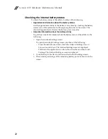
• “Checking the internal battery status” on page 22
Checking the Computer AC Charger
When you use the computer AC Charger to charge the tablet but no power is
charged, see the instructions in this topic to check the computer AC Charger.
To check the computer AC Charger, do the following:
1.
Disconnect the micro-USB cable from the tablet.
2.
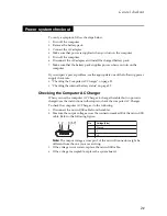
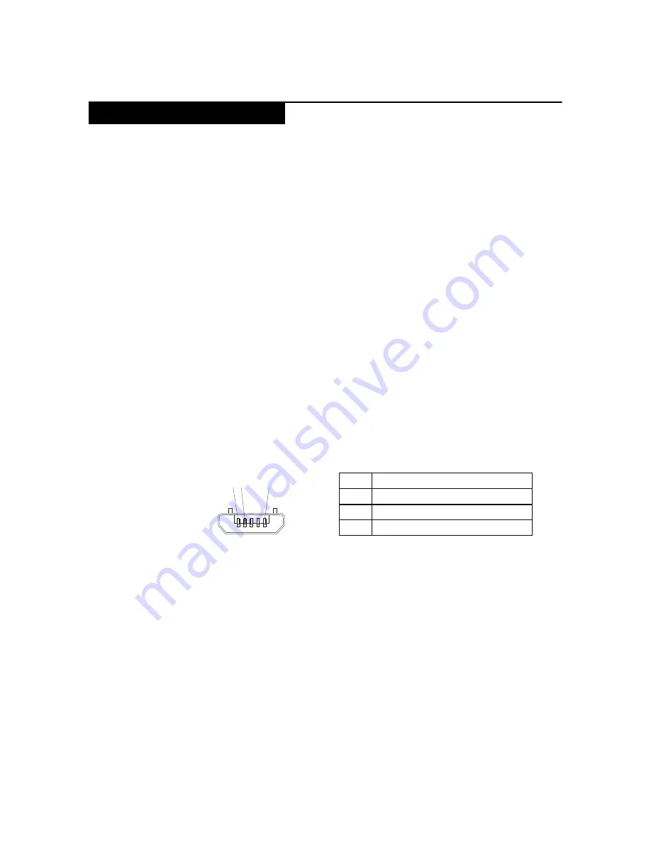
Measure the output voltage across the connector marked B of the micro-USB
cable. Refer to the following figure:
Note:
The output voltage across pin 3 of the micro-B connector might be
different from the one you are servicing.
3.
If the voltage is not correct, replace the micro-USB cable.
4.
If the voltage is acceptable, replace the system board.
Power system checkout
Pin
Volta
g
e (V dc)
1
Ground
2
0
3
+5
1 2
3 (5V)
Summary of Contents for YOGA Tablet 2-1371F
Page 1: ...YOGA TABLET 2 with Windows Hardware Maintenance Manual YOGA Tablet 2 1371F ...
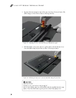
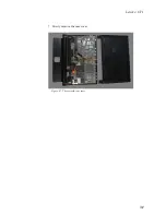
Page 35: ...Lenovo 1371 31 7 Slowly remove the rear cover Figure 1 7 The removed rear cover ...
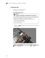
Page 49: ...Lenovo 1371 45 Figure 3 4 The removed HDMI and audio jack FPC ...
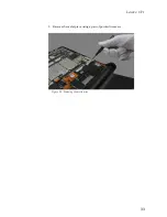
Page 59: ...Lenovo 1371 55 Figure 7 4 The removed main FPC ...
Page 62: ...Lenovo 1371 Hardware Maintenance Manual 58 Figure 8 4 The removed main HDMI FPC ...
Page 65: ...Lenovo 1371 61 Figure 9 4 The removed LCD FPC ...
Page 68: ...Lenovo 1371 Hardware Maintenance Manual 64 Figure 10 3 The removed sub board ...
Page 74: ...Lenovo 1371 Hardware Maintenance Manual 70 Figure 12 4 The removed volume key FPC ...
Page 84: ...Lenovo 1371 Hardware Maintenance Manual 80 Figure 17 4 The removed the front camera ...
Page 87: ...Lenovo 1371 83 Figure 18 4 The removed camera FPC ...
Page 90: ...Lenovo 1371 Hardware Maintenance Manual 86 Figure 19 4 The USB and power key FPC with holder ...
Page 94: ...Lenovo 1371 Hardware Maintenance Manual 90 Figure 20 5 The removed main board ...
Page 96: ...Lenovo 1371 Hardware Maintenance Manual 92 Front view Front camera Microphone Locations ...
Page 99: ...Lenovo 1371 95 ...

