50
Information SET-02
15.5 Advice on the wiring of the model railway
For the connection of the tracks, use only wires with a sufficient
cross- section to carry the intended load and slightly twist these
cables around each other. The power station (booster) should
always be placed as close to the first track feeder as possible.
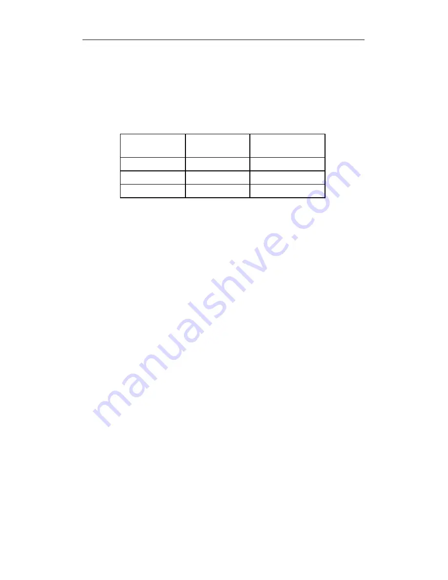
For extended routes you will need additional feeders at regular
distances from each other. Here the following rule of thumb applies:
Size
Feeder every
Minimum cross
section of the cable
N
5 ft
18 AGW
H0 / TT
6 ft
16 AGW
S and larger
9 ft
14 AGW
No radio interference suppression capacitor may be in the track
system. This capacitor is necessary only for the interference
suppression in conventional operation. If used with the
Digital plus by Lenz
®
system, however, it would only distort the
data format and interfere with the fault-free transmission of data.
Important:
A mixed digital operation using overhead and track lines is not
permitted. In such a mode of operation, if the locomotive is sitting on
the track facing in the wrong direction (which might be the case for
example after having driven through a terminal-loop), the installed
locomotive decoder can be destroyed by over-voltage! We
recommend operation using track pick-up (wheel contacts),
because the reliability of contact (and therefore the transmission of
digital signals to the locomotive decoder) is substantially greater
than it is when operating with overhead lines.
The heat produced by the amplifier in operation is normal. You must
provide sufficient air circulation around the amplifier in order to
prevent the internal protective system from reacting prematurely,
that is, during normal operation.
Do not leave your model railway system unsupervised when it
is in operation! If a short-circuit goes unnoticed, the heat
produced creates a fire risk!


