Installation
4-18
821XKlimaBA0399
K35.0082
L x
U
V W
M
3 ~
P E
R B 1 R B 2 + U G - U G
R B
M a i n s
P E
8 2 X X
K 1 0
Z 3
Z 2
Z 4
P E
P E
Z 1
P E
n
P E
P E
7
8
9
G N D 1
G N D 2
P E
V r e f
V c c
- U G
+ U G
F 1
- X 1
n
n
n
n
K 1
6 2
K 1 1 K 1 2 K 1 4
2 0 2 8 E 1 E 2 E 3 E 4 3 9
P E S
P E S
P E S
P E S
P E S
P E S
P E S
P E S
P E S
P E S
P E S
P E
P E
P E
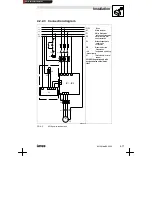
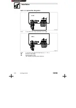
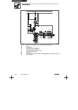
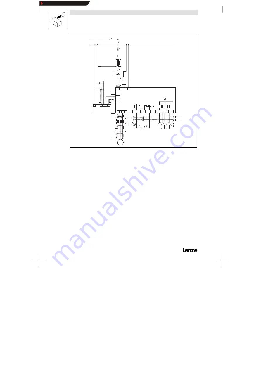
FIG 4-11
Example for an installation in accordance with the EMC regulations:
F1
Fuse
K10
Mains contactor
Z1
Mains filter ”A” or ”B”, see Accessories
Z2
Motor filter/sine filter, see Accessories
Z3
Brake module/brake chopper, see Accessories
-X1
Terminal strip in control cabinet
RB
Brake resistor
PES
HF screenbecause aufPEconnectionwitha surface aslarge aspossible (see ”Screening”inthischapter)
n
Number of phases
Show/Hide Bookmarks
Summary of Contents for 8210 HVAC Series
Page 52: ...Commissioning 5 14 821XKlimaBA0399 Show Hide Bookmarks...
Page 62: ...Commissioning 5 24 821XKlimaBA0399 Show Hide Bookmarks...
Page 64: ...During operation 6 2 821XKlimaBA0399 Show Hide Bookmarks...
Page 78: ...Configuration 7 14 821XKlimaBA0399 Show Hide Bookmarks...
Page 84: ...Troubleshooting and fault elimination 8 6 821XKlimaBA0399 Show Hide Bookmarks...
Page 88: ...Accessories 9 4 821XKlimaBA0399 Show Hide Bookmarks...
Page 92: ...Index 10 4 821XKlimaBA0399 Show Hide Bookmarks...
Page 93: ...Index 821XKlimaBA0399 10 5 Show Hide Bookmarks...
Page 94: ...Index 10 6 821XKlimaBA0399 Show Hide Bookmarks...

