Electrical installation
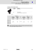
Common control terminals
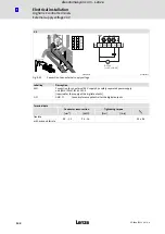
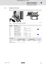
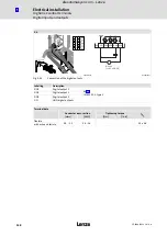
Important notes
l
123
EDS84ASC552 EN 6.0
ƒ
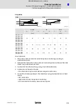
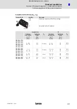
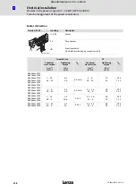
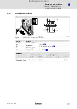
StateLine: stripping dimensions
X1
X3
X4
min.
max.
min.
max.
min.
max.
a
a
a
a
a
a
[mm]
[mm]
[mm
2
]
[
AWG
]
[mm]
[mm]
[mm
2
]
[
AWG
]
[mm]
[mm]
[mm
2
]
[
AWG
]
110
135
0.2 ... 1.5
24 ... 16
150
175
0.2 ... 1.5
24 ... 16
130
155
0.2 ... 1.5
24 ... 16
ƒ
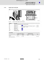
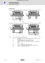
HighLine: stripping dimensions
X1
X3/X5
X4/X107
min.
max.
min.
max.
min.
max.
a
a
a
a
a
a
[mm]
[mm]
[mm
2
]
[
AWG
]
[mm]
[mm]
[mm
2
]
[
AWG
]
[mm]
[mm]
[mm
2
]
[
AWG
]
110
135
0.2 ... 1.5
24 ... 16
150
175
0.2 ... 1.5
24 ... 16
115
140
0.2 ... 1.5
24 ... 16
)
Note!
Devices including safety engineering have an increased stripping length "a":
ƒ
by 10 mm when the shield sheet is pulled out to its minimum length
ƒ
by 15 mm when the shield sheet is pulled out to its maximum length
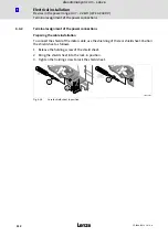
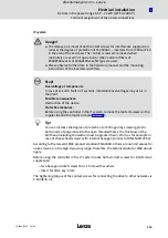
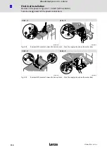
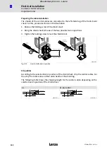
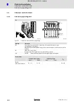
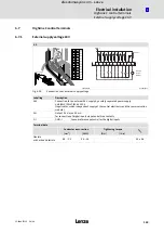
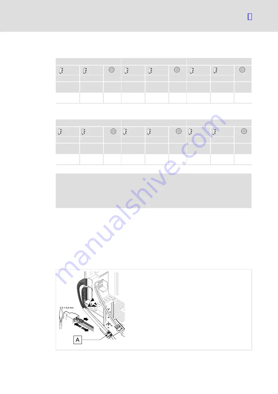
Shield and connect cables
The uncovered cable shield at the left shield lug of the stripped control cables must be
connected
0
using a (metal) cable tie for high conductivity.
As shown in the illustration, the cable ends (if required, provided with wire end ferrule)
must be inserted into the corresponding spring terminals with a suitable screwdriver (for
max. width, see illustration).
8400SLC018
Fig. 6−21
Shielding and connecting control cables
efesotomasyon.com - Lenze

