Diagnostics
Display of operating data, diagnostics
Status display via LEDs at the controller
9
l
163
EDS84ASC552 EN 6.0
9
Diagnostics
9.1
Display of operating data, diagnostics
9.1.1
Status display via LEDs at the controller
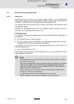
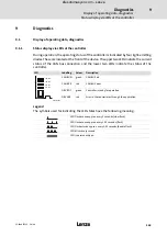
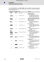
During operation, the operating status of the controller is indicated by four light−emitting
diodes.These are located at the front of the device. The upper two LEDs indicate the current
status of the CAN bus connection and the lower two LEDs indicate the status of the
controller.
LED
Labelling
Colour
Description
CAN-RUN
CAN-ERR
DRV-RDY
DRV-ERR
CAN−RUN
green
CAN−BUS o.k.
CAN−ERR
red
CAN−BUS error
DRV RDY
green
Controller is ready for operation
DRV ERR
red
Error in the controller or through the application
8400SLC026
Legend
The symbols used for indicating the LED states have the following meaning:
LED flashes once approx. every 3 seconds (slow flash)
LED flashes once approx. every 1.25 seconds (flash)
LED flashes twice approx. every 1.25 seconds (double flash)
LED blinks every second
LED is permanently on
efesotomasyon.com - Lenze

