background image

Electrical installation

Important notes
Safety notes for the installation according to U

 or U

R

6

l

 88

EDS84ASC552  EN  6.0


6.1.6

Safety notes for the installation according to U

 or U

R

J

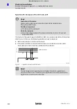
Warnings!

ƒ

The device has no overspeed protection.

ƒ

Must be provided with external or remote overload protection.

ƒ

The integral solid state protection does not provide branch circuit protection
and that branch circuit protection has to be provided externally in
accordance with manufacturers instructions, the National Electrical Code
and any additional codes.

ƒ

Branch Circuit Protection:
– Suitable for use on a circuit capable of delivering not more than 5000 rms

Symmetrical Amperes, 240 V Maximum (240 V devices).

– Suitable for use on a circuit capable of delivering not more than 5000 rms

Symmetrical Amperes, 400 V/500 V Maximum (400/500 V devices).

– Suitable for use on a circuit capable of delivering not more than 50k rms

Symmetrical Amperes, 240 V Maximum when protected by CC, J, T or R
Class Fuses or when protected by a circuit breaker having an interrupting
rating not less than 50k rms Symmetrical Amperes, 240 Volts Maximum
(240 V devices).

– Suitable for use on a circuit capable of delivering not more than 50k rms

Symmetrical Amperes, 500 V Maximum when protected by CC, J, T or R
Class Fuses or when protected by a circuit breaker having an interrupting
rating not less than 50k rms Symmetrical Amperes,
480/277 V Y Maximum (400/500 V devices).

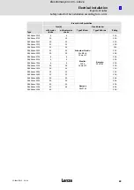
Branch Circuit Short Circuit Protection with fuses in accordance with UL248
or circuit breaker, 400/480 V Y Maximum, in accordance with UL489.
Voltage of the fuses or circuit breaker must at least be suitable with the
input voltage of the drive. The specific fuse/circuit breaker sizes and
allowable circuit breaker manufacturer and types for each inverter are
shown in the table below.

ƒ

For information on the protection level of the internal overload protection
for a motor load, see the corresponding Manual or Online Help. This
function has to be activated; i. e. the reaction must be changed from
"Warning" (factory setting) to "Fault".

ƒ

For information on rating and proper connection of the thermal protector
(only for connection to motors having integral thermal protection), see the
corresponding Manual or Online Help.

ƒ

Shall be installed in a pollution degree 2 macro−environment.

ƒ

Maximum surrounding air temperature: 55 °C.

ƒ

Use 75 °C copper wire only, except for control circuits.

ƒ

Control card protection:
– External fuse for 24 V DC supply voltage of control terminal X107.
– Rated 4 A DC fuse UL248−14.

ƒ

Safety card protection:
– External fuse for 24 V DC supply voltage of control terminal X80.
– Rated 4 A DC fuse UL248−14.
– Functional Safety is evaluated according to standards listed in section

"Safety engineering".

efesotomasyon.com - Lenze

Summary of Contents for 8400 HighLine C

Page 1: ...EDS84ASC552 A4K A4K Hardware Manual 8400 0 25 22 kW l E84Axxxx StateLine C HighLine C 8400 frequency inverter L force Drives efesotomasyon com Lenze...

Page 2: ...0Fig 0Tab 0 efesotomasyon com Lenze...

Page 3: ...of control terminals 20 3 4 Identification 21 3 5 Type code 22 4 Technical data 23 4 1 General data and operating conditions 23 4 2 Rated data 27 4 2 1 Overview 27 4 2 2 Operation at rated mains volta...

Page 4: ...technique 79 6 Electrical installation 82 6 1 Important notes 82 6 1 1 Electrical isolation 85 6 1 2 Device protection 87 6 1 3 Maximum motor cable length 87 6 1 4 Motor protection 87 6 1 5 Interactio...

Page 5: ...n 141 7 2 Quick commissioning 144 7 2 1 Keypad control 145 7 2 2 Terminal control 147 8 Braking operation 149 8 1 Braking operation without additional measures 149 8 2 Braking operation with external...

Page 6: ...ting mode 171 10 5 Technical data 172 10 6 Electrical installation 173 10 7 Certification 174 11 Accessories overview 175 11 1 Overview 175 11 2 Mains chokes 176 11 3 RFI filters 177 11 4 Sinusoidal f...

Page 7: ...range I Tip Documentation and software updates for further Lenze products can be found on the Internet in the Services Downloads area under http www Lenze com 1 1 Document history Material number Ver...

Page 8: ...rmation Type of information Writing Examples notes Notation of numbers Decimal separator Point The decimal point is always used For example 1234 56 Warnings UL warnings J Are only given in English UR...

Page 9: ...similar or the same for different versions or device sizes e g mechanical installation or power terminals Abbreviation Meaning Cat Category according to EN ISO 13849 1 OSSD Output Signal Switching Dev...

Page 10: ...in death or serious personal injury if the corresponding measures are not taken Stop Danger of property damage Reference to a possible danger that may result in property damage if the corresponding me...

Page 11: ...are persons who are familiar with the assembly installation commissioning and operation of the product and who have the qualifications necessary for their occupation Observe all specifications in this...

Page 12: ...an be obtained from the nameplate and the documentation They must be strictly observed Warning Controllers are products which can be installed in drive systems of category C2 according to EN 61800 3 T...

Page 13: ...ken e g separation from the environment through double or reinforced insulation or separation from the supply system by means of a transformer Operation If necessary systems including controllers must...

Page 14: ...y explosive atmospheres is prohibited unless they are expressly intended for such use follow additional instructions Low voltage machines are components for installation into machines as defined in th...

Page 15: ...of other machines next to the drive system must not be taken in immediately Electrical connection All operations must only be carried out by qualified and skilled personnel on the low voltage machine...

Page 16: ...Vibrational severities veff 3 5 mm s Pr 15 kW or 4 5 mm s Pr 15 kW are acceptable if the clutch is activated If deviations from normal operation occur e g increased temperatures noises vibrations find...

Page 17: ...otors at low speed Protection of the machine system Drives can reach dangerous overspeeds e g setting of high output frequencies in connection with motors and machines unsuitable for such conditions T...

Page 18: ...d safety Safe torque off STO Operating modes VFCplus V f open loop linear and square law SLVC sensorless vector control torque speed VFCplus V f closed loop for speed controlled applications SC servo...

Page 19: ...Mains DC bus voltage for 400V devices For devices in device size 6 18 5 22 kW the terminal strip is not pluggable 105 117 X101 Relay output 125 X105 Motor external brake resistor For devices in devic...

Page 20: ...er enable 137 External 24V supply of the control electronics internal 24V supply fused via PTC X6 DIAG Diagnostic interface 127 x107 24 V brake supply 140 BD1 Connection for DC brake coil BD2 MMI Slot...

Page 21: ...2 EN 6 0 3 4 Identification The type data used in this manual refer to the nameplate which is placed at the front of the controller Fig 3 1 8400SLC007 Fig 3 1 Nameplate position Type designation Hardw...

Page 22: ...E installation D Push trough technique C Cold plate technique Power e g 251 25 x 101 W 0 25 kW 222 22 x 102 W 2 2 kW Voltage class 2 230 240 V 1 N PE AC 0 25 2 2 kW 4 400 500 V 3 PE AC 0 37 22 kW Amb...

Page 23: ...d error acknowledgement is required Control terminals full Protective measures against Short circuit Earth fault Overvoltage Motor stalling Motor overtemperature PTC or thermal contact I2t monitoring...

Page 24: ...5 13 2 Hz amplitude 1 mm 13 2 100 Hz acceleration resistant up to 0 7 g EN 61800 5 1 10 57 Hz amplitude 0 075 mm 57 150 Hz acceleration resistant up to 10 m s2 1 g Requirements on the motor cable Cap...

Page 25: ...4 4 1 kV 5 kHz Control terminals EN 61000 4 4 2 kV 5 kHz Surge Power terminals EN 61000 4 5 1 2 50 s 1 kV phase phase 2 kV phase PE Control terminals EN 61000 4 5 1 2 50 s 1 kV Operation on public sup...

Page 26: ...r Maximum torque 1 8 x MN for 60 s 2 1 x MN for 3 s if rated motor power rated controller power Setting range 1 10 in the speed range 3 50 Hz Sensorless vector control speed Minimum output frequency 0...

Page 27: ...400 500 50 60 1 8 1 4 1 4 1 1 3 E84AVxxx5514 400 500 50 60 2 7 2 2 2 0 1 7 3 E84AVxxx7514 400 500 50 60 3 6 2 9 2 7 2 2 3 E84AVxxx1124 400 500 50 60 4 4 3 6 3 3 2 7 3 E84AVxxx1524 400 500 50 60 5 5 4...

Page 28: ...3 E84AVxxx1524 0 400 500 0 1000 3 9 3 1 2 9 2 3 3 E84AVxxx2224 0 400 500 0 1000 5 6 4 5 4 2 3 4 3 E84AVxxx3024 0 400 500 0 1000 7 3 5 8 5 5 4 4 3 E84AVxxx4024 0 400 500 0 1000 9 5 7 6 7 1 5 7 3 E84AV...

Page 29: ...512 45 20 E84AVxxx3712 50 E84AVxxx5512 60 E84AVxxx7512 75 E84AVxxx1122 95 E84AVxxx1522 110 E84AVxxx2222 140 E84AVxxx3714 50 E84AVxxx5514 65 E84AVxxx7514 80 E84AVxxx1124 95 E84AVxxx1524 105 E84AVxxx222...

Page 30: ...ith external mains choke without external mains choke U V W 4 pol ASM Type ILN A ILN A SaN kVA PaN kW E84AVxxx2512 3 0 3 4 0 6 0 25 E84AVxxx3712 4 2 5 0 0 9 0 37 E84AVxxx5512 5 0 5 3 1 1 0 55 E84AVxxx...

Page 31: ...Switching frequency If the maximum heatsink temperature is reached the switching frequency is reduced to 4 kHz In the setting x kHz var in C00018 the switching frequency is reduced dynamically Rated d...

Page 32: ...Use of PVC insulated copper cables conductor temperature 70 C ambient temperature 45 C no bundling of cables or cores two loaded cores Smaller cable cross sections are not permissible for technical r...

Page 33: ...ated copper cables conductor temperature 70 C ambient temperature 45 C no bundling of cables or cores two loaded cores Smaller cable cross sections are not permissible for technical reasons 2 Use UL a...

Page 34: ...2 0 1 1 E84AVxxx1524 3 9 5 5 2 4 1 5 E84AVxxx2224 5 1 7 3 3 5 2 2 E84AVxxx3024 7 0 9 8 4 6 3 0 E84AVxxx4024 8 8 13 1 5 9 4 0 E84AVxxx5524 12 0 18 8 1 5 5 E84AVxxx7524 15 0 20 0 10 3 7 5 E84AVxxx1134...

Page 35: ...power U V W Motor power 4 pol ASM IDC A SaN kVA PaN kW E84AVxxx3714 2 2 0 8 0 37 E84AVxxx5514 3 3 1 1 0 55 E84AVxxx7514 4 4 1 5 0 75 E84AVxxx1124 5 4 2 0 1 1 E84AVxxx1524 6 7 2 4 1 5 E84AVxxx2224 8 9...

Page 36: ...xxx5524 13 0 26 0 13 0 26 0 13 0 19 5 8 7 11 7 E84AVxxx7524 16 5 33 0 16 5 33 0 16 5 26 4 11 0 16 5 E84AVxxx1134 23 5 47 0 23 5 47 0 23 5 32 9 15 7 21 2 E84AVxxx1534 32 0 64 0 32 0 57 1 32 0 43 2 21 3...

Page 37: ...4 E84AVxxx4024 47 15 4 11 2 13 0 9 4 E84AVxxx5524 47 15 4 11 2 13 0 9 4 E84AVxxx7524 27 26 9 19 5 26 9 19 5 E84AVxxx1134 27 26 9 19 5 26 9 19 5 E84AVxxx1534 18 40 3 29 2 40 3 29 2 E84AVxxx1834 15 48 3...

Page 38: ...s are recommendations only Other dimensioning values laying systems are possible e g according to VDE 0298 4 The cable cross sections apply under the following conditions Use of PVC insulated copper c...

Page 39: ...lues are recommendations only Other dimensioning values laying systems are possible e g according to VDE 0298 4 The cable cross sections apply under the following conditions Use of PVC insulated coppe...

Page 40: ...2 0 1 1 E84AVxxx1524 3 1 4 4 2 4 1 5 E84AVxxx2224 4 1 5 8 3 5 2 2 E84AVxxx3024 5 6 7 8 4 5 3 0 E84AVxxx4024 7 0 10 5 5 9 4 0 E84AVxxx5524 9 6 14 4 8 1 5 5 E84AVxxx7524 12 0 16 0 10 3 7 5 E84AVxxx1134...

Page 41: ...power U V W Motor power 4 pol ASM IDC A SaN kVA PaN kW E84AVxxx3714 1 7 0 8 0 37 E84AVxxx5514 2 7 1 1 0 55 E84AVxxx7514 3 6 1 5 0 75 E84AVxxx1124 4 4 2 0 1 1 E84AVxxx1524 5 4 2 4 1 5 E84AVxxx2224 7 1...

Page 42: ...Vxxx5524 10 4 26 0 10 4 24 1 10 4 15 2 6 9 9 0 E84AVxxx7524 13 2 33 0 13 2 30 5 13 2 20 6 8 8 12 7 E84AVxxx1134 18 8 47 0 18 8 43 5 18 8 25 6 12 5 16 2 E84AVxxx1534 25 6 64 0 25 6 49 0 25 6 33 6 17 1...

Page 43: ...3 E84AVxxx4024 47 16 8 13 3 13 0 10 3 E84AVxxx5524 47 16 8 13 3 13 0 10 3 E84AVxxx7524 27 29 3 23 1 29 3 23 1 E84AVxxx1134 27 29 3 23 1 29 3 23 1 E84AVxxx1534 18 43 9 34 7 43 9 34 7 E84AVxxx1834 15 52...

Page 44: ...s are recommendations only Other dimensioning values laying systems are possible e g according to VDE 0298 4 The cable cross sections apply under the following conditions Use of PVC insulated copper c...

Page 45: ...lues are recommendations only Other dimensioning values laying systems are possible e g according to VDE 0298 4 The cable cross sections apply under the following conditions Use of PVC insulated coppe...

Page 46: ...Hz out 0 1 IOUT IOUT IaM IaM IaM02 IaM04 IaM08 IaM016 IaM0v IaM2 IaM4 IaM8 IaM16 IaMv 8400GG084 Fig 4 1 Currentderating characteristics 0 Derating curve depending on the fixed switching frequency 1 D...

Page 47: ...and ULN 400V 2 kHz 4 kHz 8 kHz 16 kHz Type IaM02 IaM2 IaM04 IaM4 IaM08 IaM8 IaM016 IaM16 E84AVxxx3714 2 6 2 6 2 6 2 6 1 5 2 6 1 0 2 1 E84AVxxx5514 3 6 3 6 3 6 3 6 2 1 3 6 1 4 3 0 E84AVxxx7514 4 8 4 8...

Page 48: ...24 19 5 26 0 13 1 24 1 9 0 15 2 4 8 9 0 E84AVxxx7524 24 8 33 0 19 3 30 5 12 7 20 6 7 4 12 7 E84AVxxx1134 35 3 47 0 24 7 43 5 16 2 25 6 9 6 16 2 E84AVxxx1534 48 0 64 0 34 9 49 0 23 4 33 6 13 1 20 8 E84...

Page 49: ...8 E84AVxxx2224 8 4 11 2 E84AVxxx3024 11 0 14 6 E84AVxxx4024 14 3 19 0 E84AVxxx5524 19 5 26 0 E84AVxxx7524 24 8 33 0 E84AVxxx1134 35 3 47 0 E84AVxxx1534 48 0 64 0 E84AVxxx1834 58 5 78 0 E84AVxxx2234 7...

Page 50: ...g of the apparent motor current for pulse loads continuous moving averaging of the apparent motor current for permanent loads Type of load Load cycle Monitoring function Condition Code Pulse load 15 s...

Page 51: ...t period Dt2 Unloading current period Permanent load 180 s cycle Calculation equation 2 Peak current C Dt3 D Dt4 Dt3 Dt4 x 100 3 Unloading current Dt3 Peak current period Dt4 Unloading current period...

Page 52: ...Mains DC bus voltage for 400V devices For devices in device size 6 18 5 22 kW the terminal strip is not pluggable 1 X101 Relay output 1 X10⁵ Motor external brake resistor For devices in device size 6...

Page 53: ...hLine C X1 System bus CANopen 1 1 S1 System bus settings CANopen 1 1 X3 Analog inputs voltage current 1 1 2 2 Analog outputs voltage current 1 2 2 10 V reference voltage 1 1 X4 Digital inputs 4 Digita...

Page 54: ...voltage pulses Suppressor diode 36 V bidirectional Polarity reversal protection When polarity is reversed no function and no destruction Current consumption Approx 0 6 A during operation Max 1 5 A st...

Page 55: ...curacy 0 1 mA Electric strength of external voltage 7 V permanent A D converter 10 bit resolution Error 1 digit 0 1 relating to the final value X3 GA GND reference potential for analog signals 4 6 3 A...

Page 56: ...lue X4 DO1 Digital output In accordance with IEC61131 2 type 1 max 50 mA External voltage protected Up to 30 V Integrated polarity reversal protection diode for switching inductive loads Isolation 85...

Page 57: ...ce potential for digital signals Labelling Feature Rated value X4 24O Connection for external 24 V supply voltage by a safely separated Power supply unit required for the supply of the digital outputs...

Page 58: ...X3 GA GND reference potential for analog signals 4 7 3 Analog outputs Labelling Features Rated value X3 O1U O2U Output voltage 0 10 V Output current 2 mA Capacitive load max 1 F Voltage 0 V Display 0...

Page 59: ...gnals 4 7 5 Digital outputs Labelling Features Rated value X4 DO1 DO2 DO3 Digital output 1 2 3 for operation of the digital outputs an external voltage source is required 57 In accordance with IEC6113...

Page 60: ...A DC Capacity to be charged 1 F X107 BD1 X107 BD2 24 V voltage output for connecting a motor holding brake via potential free contacts The brake output can also be used as a potential free digital out...

Page 61: ...nstallation of filters Regular cleaning Possible mounting position Vertical on the mounting plate mains connections at the top motor connection at the bottom Maintain the specified free spaces above a...

Page 62: ...1 Assembly in built in technique standard You can choose between three variants for mounting the built in unit version of the controllers Assembly without filter in standard technique Assembly with f...

Page 63: ...and washer assemblies or hexagon socket screws with washers are recommended How to proceed 1 Prepare the fixing holes on the mounting surface 2 Screw the controller directly to the mounting surface 8...

Page 64: ...ssignment RFI filter Type SD LD LL E84AVxxx2512 E84AZESR3712SD E84AZESR3712LD E84AZESR3712LL E84AVxxx3712 E84AVxxx5512 E84AZESR7512SD E84AZESR7512LD E84AZESR7512LL E84AVxxx7512 E84AVxxx1122 E84AZESR22...

Page 65: ...washers Do not yet tighten the screws 2 Mount the filter onto the prepared mounting plate Only tighten the screws hand tight 3 Loosen the two screw and washer assemblies to fix the standard device on...

Page 66: ...LL E84AVxxx2512 E84AZESR3712SD E84AZESR3712LD E84AZESR3712LL E84AVxxx3712 E84AVxxx5512 E84AZESR7512SD E84AZESR7512LD E84AZESR7512LL E84AVxxx7512 E84AVxxx1122 E84AZESR2222SD E84AZESR2222LD E84AZESR2222...

Page 67: ...sher assemblies or M5 hexagon socket screws with washers for the standard device Do not yet tighten the screws 2 Remove the screw and washer assemblies from the filter to fix the standard device 3 Mou...

Page 68: ...d 2 Insert the 8400 frequency inverter into the mounting cutout 3 Tighten with 6 screw and washer assemblies M5 x 10 cross screw connection recommended 4 Seal the screws to ensure the IP54 enclosure o...

Page 69: ...n contact area max deviation 0 05mm Connect the collective cooler with the drive controller with all the required screwed joints Observe the thermal resistance Rth according to the table The data incl...

Page 70: ...nd cooling plate of the controller before you screw the controller onto the cooler to troller on the cooler to keep the heat transfer resistance as low as possible For this purpose a standard heat con...

Page 71: ...ssembly in built in technique standard You can choose between three variants for mounting the built in unit version of the controllers Assembly without filter in standard technique Assembly with filte...

Page 72: ...r assemblies or hexagon socket screws with washers are recommended How to proceed 1 Prepare the fixing holes on the mounting surface 2 Screw the controller directly to the mounting surface 8400GG065 F...

Page 73: ...t ensure a durable mechanical connection Screw and washer assemblies or hexagon socket screws with washers are recommended Assignment RFI filter Type SD LD LL E84AVxxx3024 E84AZESR5524SD E84AZESR5524L...

Page 74: ...shers Do not yet tighten the screws 2 Mount the filter onto the prepared mounting plate Only tighten the screws hand tight 3 Loosen the two screw and washer assemblies to fix the standard device on th...

Page 75: ...crew and washer assemblies or hexagon socket screws with washers are recommended Assignment RFI filter Type SD LD LL E84AVxxx3024 E84AZESR5524SD E84AZESR5524LD E84AVxxx4024 E84AVxxx5524 E84AVxxx7524 E...

Page 76: ...er assemblies or M5 hexagon socket screws with washers for the standard device Do not yet tighten the screws 2 Remove the screw and washer assemblies from the filter to fix the standard device 3 Mount...

Page 77: ...oceed 1 Prepare mounting cutout and mounting holes threaded holes M5 recommended 2 Insert the 8400 frequency inverter into the mounting cutout 3 Tighten with 6 screw and washer assemblies M5 x 10 cros...

Page 78: ...ration 5 l 78 EDS84ASC552 EN 6 0 8400GG069 Fig 5 10 Dimensions Assembly in push trough technique for devices in the power range 7 5 15kW a b c c1 c2 d e f g h kW mm mm mm mm mm mm mm mm mm mm kg E84AV...

Page 79: ...t least as big as the cooling plate of the drive controller Even contact area max deviation 0 05mm Connect the collective cooler with the drive controller with all the required screwed joints Observe...

Page 80: ...max 75 C Note Apply heat conducting paste onto the cooler and cooling plate of the controller before you screw the controller onto the cooler to troller on the cooler to keep the heat transfer resista...

Page 81: ...late technique 5 l 81 EDS84ASC552 EN 6 0 8400GG068 Fig 5 12 Dimensions Assembly in cold plate technique for devices in the power range 7 5 15kW a b c c1 d e f kW mm mm mm mm mm mm mm kg E84AVxxC7524 E...

Page 82: ...ge current to earth PE is 3 5 mA AC or 10 mA DC Possible consequences Death or severe injuries when the device is touched in the event of a fault Protective measures Implement the actions required in...

Page 83: ...nal strips Plugging or removing the terminal strips during operation can cause high voltages and arcing Possible consequences Damage of the devices Protective measures Switch off device Only plug or r...

Page 84: ...supply side and on the motor side Note Switching on the controller motor side is permissible for safety shutdown emergency stop and for operation of several motor on the controller only in V f operat...

Page 85: ...nal X106 is used e g to connect an external PTC thermistor or a thermal contact ensure at least one basic insulation to the motor or mains potential to not restrict the protective separation of the co...

Page 86: ...ntrol X1 System bus CANopen Isolation by functional insulation towards other control terminals X3 Analog IO X4 Digital IO 24 V external supply The degree of insulation of the voltage source influences...

Page 87: ...permissible length of the motor cable is as follows 50 m shielded 100 m unshielded Note For compliance with EMC regulations the permissible cable lengths must be changed 6 1 4 Motor protection Extens...

Page 88: ...es or when protected by a circuit breaker having an interrupting rating not less than 50k rms Symmetrical Amperes 480 277 V Y Maximum 400 500 V devices Branch Circuit Short Circuit Protection with fus...

Page 89: ...eller FAZ C Charact C Siemens 3RV1742 15 A E84AVxxx3712 10 10 15 A E84AVxxx5512 10 10 15 A E84AVxxx7512 15 15 15 A E84AVxxx1122 20 20 20 A E84AVxxx1522 25 25 25 A E84AVxxx2222 30 30 30 A E84AVxxx3714...

Page 90: ...an overlap rate 70 and an overlap angle of 90 Keeping unshielded cable ends as short as possible Use system cables or shielded cables for these connections Motor Feedback systems Motor holding brake...

Page 91: ...rface as large as possible 2 Terminal for motor PE 3 PE of the motor cable 4 Shield of the motor cable 5 Shielded motor cable low capacitance Core core 1 5 mm2 75 pF m from 2 5 mm2 100 pF m core shiel...

Page 92: ...be connected to the mains via unshielded single cores or unshielded cables When a mains filter or RFI filter is used shield the cable between mains filter or RFI filter and controller if its length ex...

Page 93: ...t the shield to the conductive and earthed mounting plate in the control cabinet The motor cable is optimally installed if it is separated from mains cables and control cables it only crosses mains ca...

Page 94: ...ctly The shield connections of the control cables must be at a distance of at least 50 mm from the shield connections of the motor cables and DC cables Connect the shield of digital input and output c...

Page 95: ...lled if it is separated from mains cables and control cables it crosses mains cables and control cables at right angles Always install cables close to the mounting plate reference potential as freely...

Page 96: ...gnal cables in parallel and only cross at right angles The cables of a 24 V power supply unit plus and minus cable must be installed closely together over their entire length in order that no loops ma...

Page 97: ...the space between the cables must be If cables for different signal types are routed in parallel the interferences can be minimized by means of a metal barrier or separated cable ducts Cover Barrier w...

Page 98: ...DE 0160 Wiring on the motor side Stop The motor cable is highly susceptible to interference Therefore you will achieve an optimum wiring on the motor side if you exclusively use shielded and low capac...

Page 99: ...nt part with a minimum distance of 100 mm Use motor choke motor filter Install additional unshielded cables inside the motor cable e g for motor temperature monitoring Install and shield additional ca...

Page 100: ...1 N PE AC 230 V L1 N L1 N PE E84AVSCxxxx 2 K Z F1 PE X100 NC COM X101 NO X4 V T1 T2 X105 X106 M 3 PTC Rb M 3 J Rb1 Rb2 U W X3 GND A O1U GA A1I A1U AR 10 V 10 mA 1k 10k 0 10 V DC 24 V 19 2 30 V 24 V in...

Page 101: ...1U O1I O2U O2I 24O DO1 DO2 DO3 GO X3 X4 DC 24 V 0 10 V 1k 10k 0 10 V 10 V 10 mA DC 24 V 19 2 28 8 V NC COM NO X101 Rb1 E84AV Cxxxx H 2 M 3 PTC Rb M 3 J Rb1 Rb2 3 3k 3 3k 3 3k 3 3k 3 3k 3 3k 3 3k 3 3k...

Page 102: ...devices in the power range of 0 25kW to 2 2kW can also be connected to a three phase 230V mains In this case the following conditions must be observed Both mains phases L1 and L2 must be fused If the...

Page 103: ...nnections Preparing the cable installation To connect the shield of the motor cable use the shield lug of the rear shield sheet Position the shield sheet as follows 1 Release the holding screw of the...

Page 104: ...Strip motor cable and cable for motor temperature monitoring according to specified dimensions 2 Fold back the shield of the motor cable and motor temperature cable over the cable sheath Keep unshield...

Page 105: ...eed 1 Observe the above mentioned steps regarding stripping and shielding 2 Connect a second cable to the PE connection and earth it 100 8400GG039 Fig 6 12 Connection of controllers with device sizes...

Page 106: ...by screwing plastic bolts made of polyamide into the open threaded holes The thickness of the bolt head including the washer must be greater than 3 2mm as for example in case of cheese head screws wi...

Page 107: ...U W PE U V W Motor PE PE conductor Functional earth HF shield termination by connection to PE 8400GGXx002b Terminal data PE Conductor cross section Tightening torque Conductor cross section Tightenin...

Page 108: ...aration of the control terminals The terminal X106 is connected to PE inside the device but cannot be used for protective earth Terminal X106 Labelling Description T1 T2 Motor temperature monitoring w...

Page 109: ...shield termination by connection to PE 8400GGXx002b Terminal data PE Conductor cross section Tightening torque Conductor cross section Tightening torque mm2 AWG Nm lb in mm2 AWG Nm lb in E84AVxxx2512...

Page 110: ...E X100 3 PE AC 400 V 500 V L1 L2 L3 N PE F1 F3 K Z UG L2 L3 UG F4 K K O I Rb J NC COM X101 NO X4 V T1 T2 X105 X106 M 3 PTC Rb M 3 J Rb1 Rb2 U W X3 GND A O1U GA A1I A1U AR 10 V 10 mA 1k 10k 0 10 V DC 2...

Page 111: ...J K K AR A1U A1I A2U A2I GA O1U O1I O2U O2I 24O DO1 DO2 DO3 GO X3 X4 0 10 V 1k 10k 0 10 V 10 V 10 mA DC 24 V 19 2 28 8 V NC COM NO X101 Rb1 E84AV Cxxxx H 4 3 3k 3 3k 3 3k 3 3k 3 3k 3 3k 3 3k 3 3k 24 V...

Page 112: ...nections Preparing the cable installation To connect the shield of the motor cable use the shield lug of the rear shield sheet Position the shield sheet as follows 1 Release the holding screw of the s...

Page 113: ...xxx1834 E84AVxxx2234 30 110 16 195 16 160 30 10 How to proceed 1 Strip motor cable and cable for motor temperature monitoring according to specified dimensions 2 Fold back the shield of the motor cabl...

Page 114: ...connection and earth it 110 8400GG059 Fig 6 17 Connecting controllers of device size 4 6 to protective earth Mains connection Terminal X100 Labelling Description PE L1 L2 L3 Connection of the mains p...

Page 115: ...ction of the device Protective measures Before using the controller in the IT system remove the contact screws on the supply side and the motor side Fig 6 18 I Tip You can increase the degree of prote...

Page 116: ...116 EDS84ASC552 EN 6 0 X100 IT X105 IT E8400GG006 E8400GG014 Fig 6 18 Removal of the contact screws for device sizes 1 3 on the supply side and on the motor side X100 IT X105 IT 8400GG055 8400GG060 F...

Page 117: ...cross section Tightening torque Conductor cross section Tightening torque mm2 AWG Nm lb in mm2 AWG Nm lb in E84AVxxx3714 E84AVxxx5514 E84AVxxx7514 E84AVxxx1124 E84AVxxx1524 E84AVxxx2224 1 2 5 18 12 0...

Page 118: ...r cross section Tightening torque Conductor cross section Tightening torque mm2 AWG Nm lb in mm2 AWG Nm lb in E84AVxxx3714 E84AVxxx5514 E84AVxxx7514 E84AVxxx1124 E84AVxxx1524 E84AVxxx2224 1 2 5 18 12...

Page 119: ...ice but cannot be used for protective earth Terminal X106 Labelling Description T1 T2 Motor temperature monitoring with PTC element type A sensor switching performance acc to EN 60947 8 for type A tri...

Page 120: ...on Tightening torque mm2 AWG Nm lb in mm2 AWG Nm lb in E84AVxxx3714 E84AVxxx5514 E84AVxxx7514 E84AVxxx1124 E84AVxxx1524 E84AVxxx2224 1 2 5 18 12 0 5 4 4 3 5 x 0 6 1 6 18 10 1 7 15 PZ 2 7 x 1 E84AVxxx3...

Page 121: ...e but cannot be used for protective earth Design of the cables The cables used must comply with the approvals required for the location e g UL The effectiveness of a shielded cable is reached by Provi...

Page 122: ...ield sheet into one of the two possible lock in positions 3 Tighten the holding screw to lock the shield sheet 8400GG018 Fig 6 20 Locate shield sheet in position Strip cables According to the selected...

Page 123: ...te Devices including safety engineering have an increased stripping length a by 10 mm when the shield sheet is pulled out to its minimum length by 15 mm when the shield sheet is pulled out to its maxi...

Page 124: ...H CG d c b a 64 32 16 8 4 2 1 Baud CAN Adress O N 8400HLC048 8400SLC041 Fig 6 22 CANopen connection Terminal data Conductor cross section Tightening torque mm2 AWG Nm lb in flexible 0 2 1 5 24 16 2 5...

Page 125: ...contact of relay AC 250 V 3 A DC 24V 2A DC 240 V 0 16 A According to UL508C 3 A 250 V AC general purpose 2 A 24 V DC resistive 0 16 A 240 V DC general purpose NC Relay output NC normally closed Positi...

Page 126: ...For the switching operation of mains potentials shielded cables are sufficient To protect the relay contacts use a corresponding suppressor circuit in case of an inductive or capacitive load The serv...

Page 127: ...e g for initial commissioning The keypad serves to check or change individual settings It is directly plugged onto the controller Using the keypad the controller can be parameterised with regard to ba...

Page 128: ...rnal supply voltage Labelling Description 24E Connection for an external 24 V supply by a safely separated power supply unit SELV PELV IEC 61131 2 required for mains independent supply of the control...

Page 129: ...0k 0 10 V 8400SLC042 8400SLC043 Fig 6 25 Connection of the analog inputs and outputs Labelling Description Controller Reference voltage 10 V A1U Analog input 1 10V 55 A1I 0 20 mA 4 20 mA 55 GA GND ana...

Page 130: ...uts 0 Potentiometer with internal controller supply 1 Terminal assignment of the analog output signal e g by a measuring instrument 2 External master current selection based on a sensor signal 0 20 mA...

Page 131: ...onnection of the digital inputs and outputs Labelling Description RFR Controller enable controller inhibit always required DI1 Digital input 1 56 IEC61131 2 type 1 or two track frequency input for HTL...

Page 132: ...28 8 V S1 E84AVSC 24 V int 24E DI1 DI2 DI3 DI4 RFR 3 3k 3 3k 3 3k 3 3k 3 3k X4 GND IO DO1 GIO 24I GND IO 8400SLC017 8400xLC022 Fig 6 28 Wiring examples of the digital inputs and outputs 0 Wiring with...

Page 133: ...n to an external supply voltage Labelling Description 24E Connection for an external 24 V supply by a safely separated power supply unit SELV PELV IEC 61131 2 required for mains independent supply of...

Page 134: ...xternal supply voltage Labelling Description 24O Connection for an external 24 V supply by a safely separated power supply unit SELV PELV IEC 61131 2 required for the supply of the digital outputs GO...

Page 135: ...ontroller Reference voltage 10 V A1U Analog voltage input 1 10 V 58 A1I Analog current input 1 0 20 mA 4 20 mA A2U Analog voltage input 2 10 V A2I Analog current input 2 0 20 mA 4 20 mA GA GND analog...

Page 136: ...A X3 A2I O2I E84AVHC A2U O2U A1I O1I A1U O1U AR GA 10 V 10 mA 8400HLC012 8400HLC012 Fig 6 32 Wiring examples of the analog inputs and outputs 0 Potentiometer with internal controller supply 1 Termina...

Page 137: ...n RFR Controller enable controller inhibit always required DI1 Digital input 1 59 IEC61131 2 type 1 or two track frequency input for HTL encoder 0 100 kHz track A DI2 Digital input 2 track B DI3 Digit...

Page 138: ...GND O 8400HLC035 8400HLC045 Fig 6 34 Connection of the digital outputs Labelling Description DO1 Digital output 1 59 IEC61131 2 type 1 DO2 Digital output 2 DO3 Digital output 3 GO GND digital outputs...

Page 139: ...24I 1 6k 1 6k 3 3k E84AVHC 24O DC 24 V 19 2 28 8 V X4 DO1 DO2 DO3 GO GND O E84AVHC 8400HLC045 8400HLC045 2 24 V int 50 mA 24E DI1 DI2 DI3 DI4 RFR DC 24 V 19 2 28 8 V S1 3 3k 2 7k 2 7k 3 3k X5 GND I D...

Page 140: ...ot limited X107 24B X107 GB BD1 BD2 DC 24 V 19 2 28 8 V M 8400HLC037 8400HLC045 Labelling Description 24B Connection for external 24 V supply voltage of the motor holding brake Observe correct polarit...

Page 141: ...fore connecting the mains voltage Wiring for completeness short circuit and earth fault The EMERGENCY STOP function of the entire system The motor circuit configuration star delta must be adapted to t...

Page 142: ...e complex drive tasks e g table positioning see the 8400 StateLine software manual or the 8400 HighLine software manual For detailed information on commissioning and parameterisation with the Engineer...

Page 143: ...ic operating mode is set as motor control The parameter settings are preset so that if the frequency inverter and the 50 Hz asynchronous machine match in terms of power the controller is ready for ope...

Page 144: ...ntrol 147 i e a setpoint potentiometer connected to the controller terminals is used as setpoint source Diagnostics In addition to the X400 keypad also use the LEDs on the front of the controller for...

Page 145: ...or High Low edge controlled 3 Load Lenze setting to controller Note The application actuating drive speed is implemented with the Lenze setting MCTRL Act speed val C00051 0 rpm After attaching the key...

Page 146: ...step 3 Load Lenze setting to controller Quick commissioning menu Keypad Load Lenze setting Use the down navigation key to go to code C00007 for selecting the control mode Select parameter code 00007...

Page 147: ...High Low edge controlled DI1 Fixed frequency 1 fixed frequency 3 see table below DI2 DI3 DCB DI1 DI4 all active High DI4 Direction of rotation left right CCW CW HighLine Analog inputs at X3 Assignment...

Page 148: ...e 00002 1 Parameterise with left Edit function key MCTRL Act speed val C00051 0 rpm When the Lenze setting is loaded the display goes off for a short time When the display goes on again the main menu...

Page 149: ...thout using an external brake resistor Code C00036 can be used to select the braking current The maximum braking torque to be realised by the DC braking current amounts to approx 20 30 of the rated mo...

Page 150: ...rake resistor Adapt the switching threshold to the mains voltage C00173 C00714 see software manual 8 2 1 Operation at rated mains voltage 230 V Switching threshold VBRmax 380 V adjustable RBmin IBRmax...

Page 151: ...024 47 15 4 11 2 13 0 9 4 E84AVxxx4024 47 15 4 11 2 13 0 9 4 E84AVxxx5524 47 15 4 11 2 13 0 9 4 E84AVxxx7524 27 26 9 19 5 26 9 19 5 E84AVxxx1134 27 26 9 19 5 26 9 19 5 E84AVxxx1534 18 40 3 29 2 40 3 2...

Page 152: ...4 47 16 8 13 3 13 0 10 3 E84AVxxx4024 47 16 8 13 3 13 0 10 3 E84AVxxx5524 47 16 8 13 3 13 0 10 3 E84AVxxx7524 27 29 3 23 1 29 3 23 1 E84AVxxx1134 27 29 3 23 1 29 3 23 1 E84AVxxx1534 18 43 9 34 7 43 9...

Page 153: ...hm t1 tzykl w Pmax he hm 2 t1 tzykl Heat quantity Ws w Pmax he hm t1 w Pmax he hm 2 t1 Resistance Rmin v R v UDC 2 Pmax he hm Active load Can start to move independent of the drive e g unwinder Passiv...

Page 154: ...permissible value The thermostat of several brake resistors at a controller must always be connected in series Product key Rated data brake resistor Controller Brake resistor Resistor R Continuous pow...

Page 155: ...ot surface The brake resistor may get very hot For temperatures see the mounting instructions for the brake resistor Possible consequences Severe burns when touching the brake resistor Fire or smoulde...

Page 156: ...ing of a brake resistor to the controller PES HF shield termination by PE connection via shield clamp Rb1 Rb2 Terminals of the brake resistor Supply cable to the controller T1 T2 Terminals temperature...

Page 157: ...switch which is connected to one of the digital outputs of the controller The digital output must be parameterised accordingly For controllers in the HighLine version the switching operation of the b...

Page 158: ...be destroyed Apply the shield to PE on both sides Requirements with regard to the supply voltage UDC connection Always supply the motor brake control with a separate 24 V supply A common supply of the...

Page 159: ...tective function Protected against polarity reversal until DC 60 V Maximally connectable cable cross section 1 5 mm2 AWG 16 E82ZWBRE brake switch Range Values Input voltage 3 PE AC 400 V AC 320 550 V...

Page 160: ...IEC 61131 2 19 2 28 8 V Input current DC 0 1 2 6 A Output voltage DC 24 V Maximum brake current DC 2 5 A Internal control Information on the internal control can be found in chapter 12 1 from the 840...

Page 161: ...lb in M 3 BD1 BD2 F10 B6 A C6A EN 60204 1 5A UL 248 82zwbrx_10 A1 Lenze controller with digital output F10 Additional cable protection E82ZWBRE brake switch DC 180 V AC 400 V DC 225 V AC 500 V 3 PE A...

Page 162: ...BD1 V M 3 E84AVHC 24 V DC 1 5 mm GB W 24B PE X107 PES BD1 BD2 E84HLC005 E84AVHC Controller in the HighLine version F10 Cable protection in secondary circuit For dimensioning the fuse observe the stan...

Page 163: ...bus connection and the lower two LEDs indicate the status of the controller LED Labelling Colour Description CAN RUN CAN ERR DRV RDY DRV ERR CAN RUN green CAN BUS o k CAN ERR red CAN BUS error DRV RD...

Page 164: ...Device is switched on This is the controller s device state if the DC bus voltage is applied and the controller is still inhibited by the user controller inhibit OFF OperationEnabled state Operation...

Page 165: ...is stopped Quick stop is active Controller is inhibited The power outputs are inhibited Controller is ready to start ReadyToSwitchOn state Speed controller 1 in the limitation The drive is torque con...

Page 166: ...hermal motor load I2xt C00178 Time the controller was enabled elapsed time meter C00179 Time the mains was switched on power on time meter Identification data The parameters listed in the following ta...

Page 167: ...and control measures Drive based safety provides the conditions in the controls and drives to optimise the safety functions Planning and installation expenditure is reduced In comparison to the use of...

Page 168: ...rements of ISO 13849 1 and ISO 138492 This includes i a Switches relays in IP54 enclosure Control cabinet in IP54 enclosure Please refer to ISO 13849 1 and ISO 138492 for all further requirements It i...

Page 169: ...n Before putting a machine into circulation the manufacturer of the machine must carry out a hazard analysis according to the Machinery Directive 98 37 EC to find out the hazards related to the applic...

Page 170: ...trol units Active sensors Active sensors are units with two channel semiconductor outputs OSSD outputs Drive based safety integrated in this device series allows for test pulses 1 ms to monitor the ou...

Page 171: ...ate a rotating field The motor is safely switched to torqueless operation STO M SU PWM C P C 3x 3x X80 X80 E84ABSB005 Fig 10 1 Operating principle of safety unit SU Safety unit X80 Control terminals o...

Page 172: ...ures of the inputs and outputs of the safety unit Terminal Specification Unit min typ max SIA SIB Low signal V 3 0 5 High signal V 15 24 30 Input capacitance at switch off nF 4 Input delay tolerated t...

Page 173: ...eld sheet strain relief X80 Marking Description Electrical data SIA SIB GI 24O DO1 GO SIA Input first shutdown path SIA Ityp 100 mA GI GND potential for SIA SIB LOW 3 5 V HIGH 15 30 V SIB Input second...

Page 174: ...ments of the following standards Category 4 and PL e according to EN ISO 13849 1 To comply with category 4 the external wiring and the cable monitoring must meet the requirements of category 4 Ensure...

Page 175: ...00 Communication modules PROFIBUS E84AYCPM EtherCAT E84AYCET Memory module E84AYM10S M USB diagnostic adapter E94AZCUS Connecting cables EWL007x PC system bus adapter EMF2173IBxxx EMF2177IB EZAEBK1001...

Page 176: ...x1122 ELN1 0250H018 E84AVxxx1522 E84AVxxx2222 E84AVxxx3714 ELN3 1500H003 001 E84AVxxx5514 E84AVxxx7514 E84AVxxx1124 ELN3 0680H006 001 E84AVxxx1524 E84AVxxx2224 E84AVxxx3024 ELN3 0500H007 001 E84AVxxx4...

Page 177: ...xx3024 E84AZESR5524SD E84AZESR5524LD E84AVxxx4024 E84AVxxx5524 E84AVxxx7524 E84AZESR1534LD E84AVxxx1134 E84AVxxx1534 E84AVxxx1834 1 E84AVxxx2234 1 In preparation Basis of the data Voltage Voltage rang...

Page 178: ...V AC 4 8 11 0 4 0 E84AVxxx5514 E84AVxxx7514 E84AVxxx1124 E84AVxxx1524 EZS3 010A200 0 550 V AC 4 8 5 1 5 5 E84AVxxx2224 E84AVxxx3024 E84AVxxx4024 EZS3 017A200 0 550 V AC 4 8 3 1 8 5 E84AVxxx5524 E84AV...

Page 179: ...E84AVxxx3714 ERBM390R100W 390 100 15 E84AVxxx5514 ERBM390R100W E84AVxxx7514 E84AVxxx1124 ERBP180R200W 180 200 30 E84AVxxx1524 ERBP180R200W E84AVxxx2224 ERBP180R300W 300 45 E84AVxxx3024 E84AVxxx4024 E...

Page 180: ...es of identical drives Recovery of an application after device exchange The required steps of a parameter set transfer are described in the software manual To remove the memory module lever it out at...

Page 181: ...om the bus Sub D connection Suitable for Inverter Drives 8400 StateLine C and HighLine C Name EtherCATcommunication module Model designation E84AYCETV Slot MCI The EtherCAT communication module is a r...

Page 182: ...tion EZAEBK1001 Slot X6 DIAG Features Menu driven diagnostics and parameter setting Backlighted graphic display for representing information 4 navigation keys 2 context sensitive keys Adjustable RUN S...

Page 183: ...h an external 24 V supply if required Advantages of an external supply Parameter setting and diagnostics of the controller with a deenergised mains input Mains Secondary Type VLN V ILN A VDC V IDC A E...

Page 184: ...ration Display functions 163 Contactors in the motor cable 17 Control cable 94 Control terminals 54 57 121 128 133 D DC bus connection to the 117 DC supply 92 DC bus operation 23 Definition of notes u...

Page 185: ...7 requirements 24 Motor connection 107 Motor end switching on the 17 Motor power typical 30 34 40 Motor protection 17 Mounting mounting variant 66 75 mounting filter with standard technology 64 73 N N...

Page 186: ...les 104 113 122 Supply voltage 24 V external 54 57 128 133 Switch on check before switching on 141 Switching on the motor side 17 System bus CANopen 124 T Technical data 23 172 Terminals 52 Terms defi...

Page 187: ...ice Lenze Service GmbH Breslauer Stra e 3 D 32699 Extertal Germany 49 0 51 54 82 0 00 80 00 24 4 68 77 24 h helpline 49 0 51 54 82 28 00 49 0 51 54 82 11 12 Lenze Lenze de Service Lenze de www Lenze c...

Reviews: