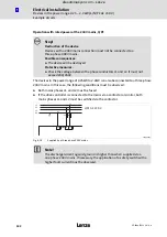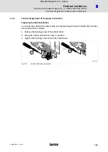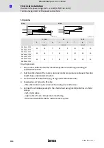
Electrical installation
Installation according to EMC (installation of a CE−typical drive system)
Shielding
l
91
EDS84ASC552 EN 6.0
Realisation
PE
PE
PE
M
3~
8
9
PES
1
2
4
7
0
6
5
3
8400SLC024
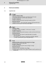
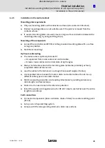
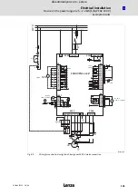
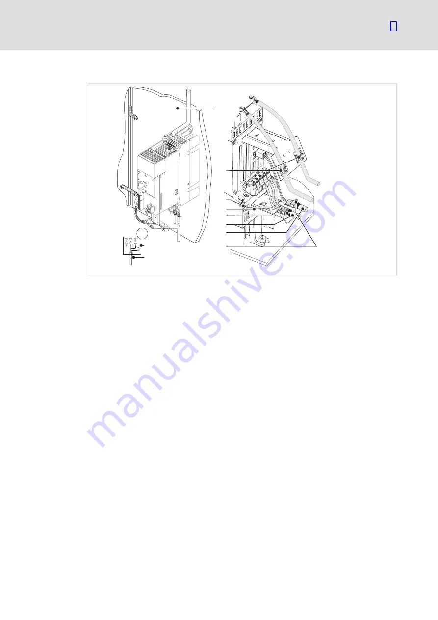
Fig. 6−2
Wiring in compliance with EMC standards
0
Mounting plate with electrically conductive surface
1
Control cables, connect shielding to the upper shield sheet (PES) with a surface as large as
possible
2
Terminal for motor PE
3
PE of the motor cable
4
Shield of the motor cable
5
Shielded motor cable, low−capacitance
(Core/core 1.5 mm
2
75 pF/m; from 2.5 mm
2
100 pF/m; core/shield
150 pF/m)
6
Shielded PTC cable or thermal contact cable (preferentially installed separately)
7
Connect cable shields to the lower shield sheet (PES) with a large surface. Preferentially use
metal cable binders from the accessories.
8
Star or delta connection as indicated on the motor nameplate
9
EMC cable gland (not included in the scope of supply)
efesotomasyon.com - Lenze

