8400 StateLine C | Reference manual
Tech
nology app
lication
s
TA "Actuating drive speed"
30
2
L
Firmware
≤
11.0
0 - D
M
S 8.0
EN - 10
/2
01
1
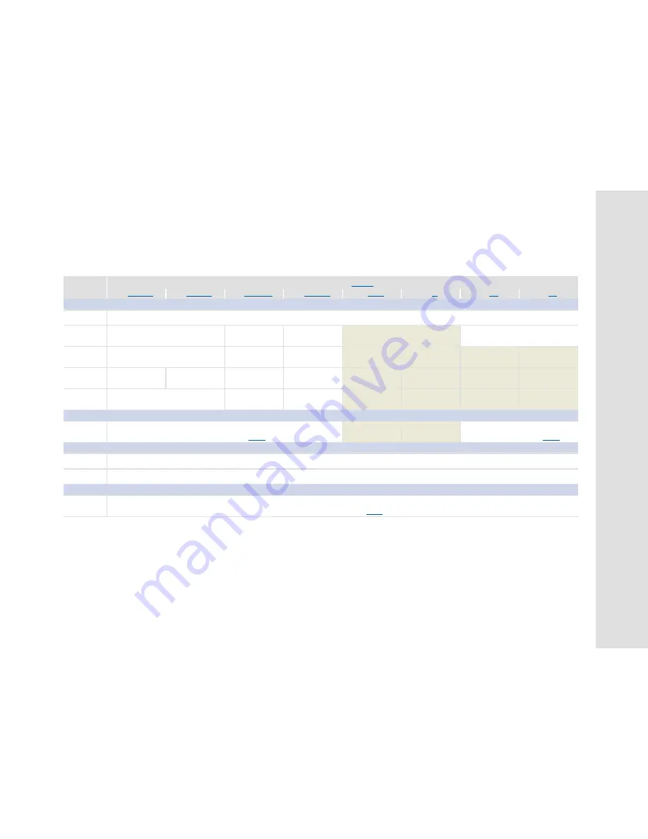
7.2.3
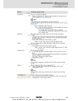
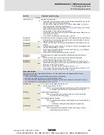
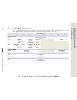
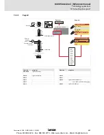
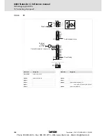
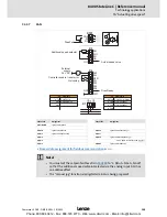
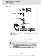
Terminal assignment of the control modes
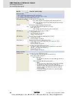
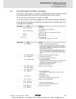
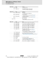
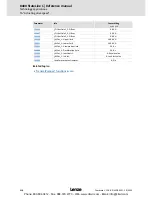
The following comparison provides information about which inputs/outputs of the application block
LA_NCtrl
are interconnected
to the digital and analog input/output terminals of the drive controller in the different control modes.
Control mode
(
C00007
)
10:
Terminals 0
12:
Terminals 2
14:
Terminals 11
16:
Terminal 16
20:
Keypad
21:
PC
30:
CAN
40:
MCI
Digital input terminals
X4/RFR
Controller enable / Reset of error message
bFailReset
X4/DI1
Fixed setpoint 1/3
bJogSpeed1
Change of direction of
rotation
bSetSpeedCcw
Fixed setpoint 1/3
bJogSpeed1
-
-
Quick stop
bSetQuickstop
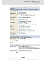
X4/DI2
Fixed setpoint 2/3
bJogSpeed2
Activate manual DC-
injection braking (DCB)
bSetDCBrake
Fixed setpoint 2/3
bJogSpeed2
-
-
-
-
X4/DI3
Activate manual DC-
injection braking (DCB)
bSetDCBrake
Quick stop
bSetQuickstop
Motor potentiometer:
Increase speed
bMPotUp
CW rotation quick stop
bRLQCw
-
-
-
-
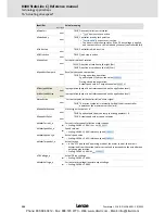
X4/DI4
Change of direction of rotation
bSetSpeedCcw
Motor potentiometer:
Decrease speed
bMPotDown
CCW rotation quick stop
bRLQCcw
-
-
-
-
Analog input terminals
X3/A1U, A1I
Main speed setpoint
nMainSetValue_a
10 V
≡
100 % reference speed (
C00011
)
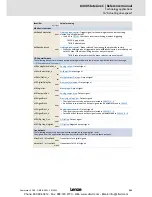
-
-
Additional speed setpoint
nAuxSetValue_a
10 V
≡
100 % reference speed (
C00011
)
Digital output terminals
X4/DO1
Status "Drive is ready"
bDriveReady
X101/COM, NO
Status "Error is pending"
bDriveFail
Analog output terminal
X3/O1U
Actual speed value
nMotorSpeedAct_a
10 V
≡
100 % reference speed (
C00011
)
Phone: 800.894.0412 - Fax: 888.723.4773 - Web: www.clrwtr.com - Email: info@clrwtr.com

