background image

Product extensions

Motor connection

The Lenze Smart Motor can be simply connected via connectors (QUICKON or M15 for power

connection, M12 for control terminals).
The power connection can alternatively be established in the terminal box via cable glands

using spring terminals.
The connections are kept easily accessible from the fan side.

4

Information on electrical installation


^

 33

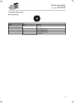
Connection via terminal box

MSEMA terminal box
Contact

Name

Meaning

1

L1

Mains connection Phase L1

2

L2

Mains connection Phase L2

3

L3

Mains connection Phase L3

PE

PE

PE conductor

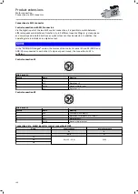
Connection via QUICKON V2 connector
The QUICKON connection enables fast and easy connection of motors. The system is easy to

cable by means of a connecting cable with the QUICKON nut.

QUICKON V2 nuts and QUICKON V2 connectors with QUICKON V2 nuts are

available as accessories.

Mains connection X3

1

2

3

PE

QUICKON V2
Contact

Name

Meaning

1

L1

Mains connection Phase L1

2

L2

Mains connection Phase L2

3

L3

Mains connection Phase L3

4

PE

PE conductor

Product extensions

Motor connection

Connection via terminal box

98

Summary of Contents for g500-H

Page 1: ...Mains operated geared motors g500 H helical geared motor Smart Motor m300 E Project planning EN...

Page 2: ......

Page 3: ...ts 25 Ventilation 26 Information on mechanical installation 32 Important notes 32 Transport 32 Installation 32 Information on electrical installation 33 Important notes 33 Connection according to EN 3...

Page 4: ...a M12 connector 100 Brakes 101 Spring applied holding brake 102 Brake resistors 104 Accessories 105 NFC adapter 105 QUICKON connector 106 UMCLN_SGG_100181 107 Product codes 108 Motor data 110 Rated da...

Page 5: ...ou will receive information regarding product extensions and accessories The document includes safety instructions which must be observed All persons working on and with the drives must have the docum...

Page 6: ...er documentation with additional information Example EDKxxx see documentation EDKxxx Layout of the safety instructions DANGER Indicates an extremely hazardous situation Failure to comply with this ins...

Page 7: ...ration High efficiency Reduction in the number of variants made easy Before now different output speeds e g for different conveying speeds were enabled by different gearbox ratios or in the case of ve...

Page 8: ...an and English can be obtained from www Lenze com or the Google Store For convenience the data records created can be archived on the smartphone and repeatedly transferred to the Lenze Smart Products...

Page 9: ...completely from the outside by means of connectors The Lenze Smart Products come with an especially clever connecting technology Phoenix Contact QUICKON Electrical installation is therefore very easy...

Page 10: ...00 g500 H100 140 g500 H140 210 g500 H210 320 g500 H320 450 g500 H450 600 g500 H600 850 g500 H850 1500 g500 H1500 3000 g500 H3000 Product name of the motor Product series Type Size Overall length Numbe...

Page 11: ...g position Oil drain plug Housing type Output flange Output shaft Connection of spring applied brake Mains connection Control terminal Brake resistor connection prewired upon delivery X5 External X4 I...

Page 12: ...The modular system Values printed in bold are standard designs Values that are not printed in bold are potential extensions some of them including a surcharge Product information The modular system 12...

Page 13: ...x 60 35 x 70 Solid shaft without keyway mm 20 x 40 20 x 40 25 x 50 25 x 50 30 x 60 35 x 70 Shaft material Steel Stainless steel Shaft sealing ring material NBR FKM Viton Output shaft bearing Standard...

Page 14: ...t without keyway mm 35 x 70 40 x 80 50 x 100 60 x 120 Shaft material Steel Stainless steel Shaft sealing ring material NBR FKM Viton Output shaft bearing Standard Reinforced Gearbox design With foot V...

Page 15: ...e is suitable for absorbing high radial and axial forces 45 Solid shaft with foot Without centring VBR With centring VAR Flange with through holes VAK Solid shaft without foot With centering VCR Flang...

Page 16: ...in mounting position M1 5 6 AEF M1 A M2 D M5 F M3 B M4 C M6 E Defined positions on the geared motor All of the defined positions refer to the areas on the geared motor in mounting position M1 A Posit...

Page 17: ...sitions of the connections Mains connection Control terminal Cable gland for terminal box QUICKON V2 connector M15 connector M12 connector E E Position of the manual release lever Product information...

Page 18: ...suitability of the process and circuit proposals All work with and on the product may only be carried out by qualified personnel IEC 60364 and CENELEC HD 384 define the qualifications of these person...

Page 19: ...otor is stopped Before working check whether all power terminals are deenergized Voltages may occur on the drive components e g capacitive caused by inverter supply Careful earthing in the marked posi...

Page 20: ...late Excessive input speeds lead to increased temperatures Do not exceed the input speeds specified on the nameplate Avoid excessive lateral forces on the gearbox shaft Align the shafts of the gearbox...

Page 21: ...basis of the forces Calculated necessary output torque Calculate intensity Determine the product on the basis of the obtained data Final configuration Check operating conditions Check Approvals Confo...

Page 22: ...rad M f F 2000 dw Frad fW x Frad max Axial force Fax N Fax Frad max x 0 5 dw Effective diameter of transmission element in mm fW Additional load factor 4Radial forces and axial forces 45 Calculate ou...

Page 23: ...name of the parameter set without file extension lsm Output speed 1 depending on the order 2600 i 500 i rpm 0 rpm 500 i 2600 i rpm CCW rotation 0 rpm STOP 0 rpm CW rotation 0 rpm Lenze Smart Motor wi...

Page 24: ...ts are primed with grey paint Slight colour differences of the components are possible Surface and corrosion protection Applications Product g500 H45 H450 g500 S130 S660 g500 B45 B450 g500 H600 H1500...

Page 25: ...polyalfaolefins basis Synthetic oil polyglycol basis Changing interval Operating hours 16000 Not later than after 3 years At an oil temperature of 70 C FUCHS Cassida Fluid GL 220 Cassida Fluid WG 460...

Page 26: ...ing gearboxes can also be ordered with combined mounting positions g500 H45 in mounting position M1 M6 A F g500 H100 H450 in mounting position M1 5 6 AEF In these gearboxes the lubricant amount has be...

Page 27: ...g500 H210 H450 Mounting position M1 A Mounting position M2 D Mounting position M3 B Filling and ventilation Control Drain Information on project planning Final configuration Ventilation 27...

Page 28: ...unting position M4 C Mounting position M5 F Mounting position M6 E Filling and ventilation Control Drain g500 H210 g500 H320 g500 H450 Information on project planning Final configuration Ventilation 2...

Page 29: ...g500 H600 H3000 Mounting position M1 A Mounting position M2 D Mounting position M3 B Filling and ventilation Check Drain Information on project planning Final configuration Ventilation 29...

Page 30: ...required in the gearbox As a result of the reduced volume of air in the gearbox this may lead to oil escaping from the ventilation at higher input speeds The oil compensation reservoir increases the...

Page 31: ...02 2000 5 400 2000 6 344 2000 6 245 2000 6 968 2000 6 864 2000 8 327 2000 7 592 2000 9 146 2000 9 010 2000 10 005 2000 10 267 2000 11 619 2000 11 356 2000 12 762 2000 12 362 3000 14 233 2000 13 673 30...

Page 32: ...parts Only use safely fixed transport aids e g eye bolts or support plates Do not damage any components during transport Avoid electrostatic discharges on electronic components and contacts Avoid impa...

Page 33: ...om the mains Check that the power terminals are deenergized before starting work When working on energized products comply with the applicable national accident prevention regulations The electrical i...

Page 34: ...ains connection M15 connector Motor MSEMA 063 42 MSEMA 080 32 Connection X3 Laying system B2 Connection type M15 connector Cable type Flexible Cable cross section Typ mm2 1 5 2 5 Min mm2 1 5 1 5 Max m...

Page 35: ...ied on the nameplate Fuse data F1 F3 Motor MSEMA 063 42 MSEMA 080 32 Cable installation in accordance with EN IEC 60204 1 Laying system B2 Fuse Characteristic gG gL Typ Rated current A 6 10 Max rated...

Page 36: ...er Characteristic gRL Typ Rated current A Max rated current A 10 16 20 Imax IN1 IN2 IN3 IN A 7 6 12 2 17 6 4Rated data 110 Use of copper cables insulated with PVC Conductor temperature 70 C ambient te...

Page 37: ...Max AWG 14 14 Mains connection M15 connector Motor MSEMA 063 42 MSEMA 080 32 Connection X3 Connection type M15 connector Cable cross section Typ AWG 16 14 Min AWG 16 16 Max AWG 14 14 Mains connection...

Page 38: ...rmes la norme NFPA 79 Protection contre les surcharges homologu e pour 125 du courant assign pleine charge La protection statique int gr e n offre pas la m me protection qu un disjoncteur Une protecti...

Page 39: ...a circuit breaker having an interrupting rating not less than 5k rms symmetrical amperes 480 Maximum see table above Marquage UL Convient une utilisation sur un circuit non susceptible de d livrer plu...

Page 40: ...into account WARNING UL marking Suitable for motor group installation on a circuit capable of delivering not more than 5k rms symmetrical amperes 480 V maximum When protected by fuses rated see table...

Page 41: ...ient temperature 40 C Site altitude 1000 m above mean sea level The selection tables indicate the mechanically permissible power levels and torques The ratings apply to the operating mode S1 acc to EN...

Page 42: ...I 2012 3032 The Restriction of the Use of Certain Hazardous Substances in Electrical and Electronic Equipment Regulations 2012 S I 2016 1091 The Electromagnetic Compatibility Regulations 2016 S I 2016...

Page 43: ...ions and safety instructions Equipotential bonding Additional M5 thread with terminal on the terminal box for connection of a 6mm PE cable Total fault current Earth leakage circuit breaker In TN syste...

Page 44: ...of pollution 2 Vibration resistance Operation EN 60721 3 3 1995 A2 1997 3M4 Transport EN 60721 3 2 1997 2M2 Vibration severity A EN IEC 60034 14 Electrical supply conditions Possibility of connection...

Page 45: ...taking into account the direction of action factor f see following diagrams higher radial forces than the values given in the tables are permissible Frad perm fw x f x Frad max Permissible axial force...

Page 46: ...700 5700 g500 H450 2440 2820 3340 4020 4660 5540 6500 7100 7100 7100 g500 H600 3820 4480 5250 6100 7260 8450 9500 9500 9500 9500 g500 H850 4700 5510 6430 7500 8860 10400 11500 11500 11500 11500 g500 H...

Page 47: ...orce Frad max N g500 H100 1000 1200 1500 1700 1700 1700 1700 1700 1700 1700 g500 H140 1300 1800 2300 2600 2600 2600 2600 2600 2600 2600 g500 H210 1400 2000 2500 3000 3000 3000 3000 3000 3000 3000 g500...

Page 48: ...0 1 25 1 30 1 35 1 40 0 30 60 90 120 150 180 210 240 270 300 330 360 f 1 00 1 05 1 10 1 15 1 20 1 25 1 30 0 30 60 90 120 150 180 210 240 270 300 330 360 f 2 stage Direction of rotation R 4 stage Direc...

Page 49: ...rection of rotation R 2 stage Direction of rotation L 4 stage Direction of rotation R 3 stage Direction of rotation L g500 H3000 1 00 1 05 1 10 1 15 1 20 1 25 1 30 1 35 1 40 0 30 60 90 120 150 180 210...

Page 50: ...869 3 413 g500 H45 MSEMA 063 42 2 7 4 115 7 0 595 7 0 21 0 26 2 3 817 4 368 g500 H45 MSEMA 063 42 2 7 4 94 2 9 0 489 9 0 27 0 33 8 3 879 5 312 g500 H45 MSEMA 063 42 2 7 4 Basic weight Number of gear s...

Page 51: ...9 800 g500 H140 MSEMA 063 42 2 11 49 9 17 0 259 17 0 35 0 43 8 3 786 10 033 g500 H45 MSEMA 063 42 2 7 4 49 7 17 0 258 17 0 68 0 68 3 3 813 10 063 g500 H100 MSEMA 063 42 2 9 4 46 7 18 0 243 18 0 73 0...

Page 52: ...211 233 3 795 38 238 g500 H320 MSEMA 063 42 2 14 12 8 67 0 66 1 67 0 210 231 3 783 39 286 g500 H210 MSEMA 063 42 2 12 12 6 68 0 65 2 68 0 81 0 89 2 3 722 39 857 g500 H100 MSEMA 063 42 2 9 4 12 4 68 0...

Page 53: ...40 154 3 793 84 732 g500 H140 MSEMA 063 42 3 14 5 7 147 29 5 147 320 400 3 761 87 906 g500 H320 MSEMA 063 42 3 14 5 7 149 29 2 149 594 594 3 917 88 826 g500 H600 MSEMA 063 42 3 29 5 7 149 29 1 149 450...

Page 54: ...066 281 416 g500 H1500 MSEMA 063 42 4 72 1 8 469 9 2 469 450 495 3 725 280 500 g500 H450 MSEMA 063 42 3 18 1 8 470 9 1 470 600 750 3 914 285 021 g500 H600 MSEMA 063 42 4 32 1 7 485 8 8 485 850 1063 3...

Page 55: ...957 625 g500 H3000 MSEMA 063 42 4 117 0 5 1682 2 5 1682 1500 1650 3 808 1020 881 g500 H1500 MSEMA 063 42 4 72 0 5 1733 2 4 1733 3000 3300 3 851 1051 817 g500 H3000 MSEMA 063 42 4 117 0 5 1860 2 3 186...

Page 56: ...190 26 589 9 799 g500 H210 MSEMA 080 32 2 19 49 7 49 0 258 49 0 99 0 124 26 113 10 063 g500 H100 MSEMA 080 32 2 16 46 9 52 0 244 52 0 207 207 26 723 10 677 g500 H320 MSEMA 080 32 2 20 46 7 52 0 243 5...

Page 57: ...231 26 085 35 095 g500 H210 MSEMA 080 32 2 19 14 2 171 73 8 171 504 554 26 408 35 214 g500 H600 MSEMA 080 32 2 35 14 1 173 72 8 173 450 495 26 244 35 689 g500 H450 MSEMA 080 32 2 24 13 5 180 69 9 180...

Page 58: ...32 3 24 5 1 477 26 0 477 600 750 26 216 99 757 g500 H600 MSEMA 080 32 3 36 4 8 500 24 8 500 850 935 26 405 104 607 g500 H850 MSEMA 080 32 3 45 4 6 521 23 8 521 450 563 26 117 109 083 g500 H450 MSEMA 0...

Page 59: ...290 397 548 g500 H1500 MSEMA 080 32 4 79 1 3 1946 6 2 1946 3000 3750 26 669 413 415 g500 H3000 MSEMA 080 32 4 124 1 1 2151 5 6 2151 3000 3750 26 581 457 048 g500 H3000 MSEMA 080 32 4 124 1 1 2306 5 3...

Page 60: ...080 32 Table content Explanation Total length L Total length of the drive without brake Motor length LB Length of the motor without brake Length of motor options L Additional length with brake Motor d...

Page 61: ...design Solid shaft with foot VBR Motor series MSEMA Motor 063 42 Total length L mm 288 Motor length LB mm 196 Motor diameter AC mm 123 Motor connection distance AD mm 141 L 4Additional lengths 96 Tech...

Page 62: ...shaft and foot centering VCR Motor series MSEMA Motor 063 42 Total length L mm 288 Motor length LB mm 196 Motor diameter AC mm 123 Motor connection distance AD mm 141 L 4Additional lengths 96 Technica...

Page 63: ...d shaft and foot flange VCK Motor series MSEMA Motor 063 42 Total length L mm 288 Motor length LB mm 196 Motor diameter AC mm 123 Motor connection distance AD mm 141 L 4Additional lengths 96 Technical...

Page 64: ...with foot VBR Motor series MSEMA Motor 063 42 080 32 Total length L mm 326 369 Motor length LB mm 183 226 Motor diameter AC mm 123 156 Motor connection distance AD mm 141 159 L 4Additional lengths 96...

Page 65: ...ot centering VAR VCR Motor series MSEMA Motor 063 42 080 32 Total length L mm 326 369 Motor length LB mm 183 226 Motor diameter AC mm 123 156 Motor connection distance AD mm 141 159 L 4Additional leng...

Page 66: ...oot flange VAK VCK Motor series MSEMA Motor 063 42 080 32 Total length L mm 326 369 Motor length LB mm 183 226 Motor diameter AC mm 123 156 Motor connection distance AD mm 141 159 L 4Additional length...

Page 67: ...nd flange VCP Motor series MSEMA Motor 063 42 080 32 Total length L mm 346 389 Motor length LB mm 183 226 Motor diameter AC mm 123 156 Motor connection distance AD mm 141 159 L 4Additional lengths 96...

Page 68: ...with foot VBR Motor series MSEMA Motor 063 42 080 32 Total length L mm 339 382 Motor length LB mm 183 226 Motor diameter AC mm 123 156 Motor connection distance AD mm 141 159 L 4Additional lengths 96...

Page 69: ...ot centering VAR VCR Motor series MSEMA Motor 063 42 080 32 Total length L mm 339 382 Motor length LB mm 183 226 Motor diameter AC mm 123 156 Motor connection distance AD mm 141 159 L 4Additional leng...

Page 70: ...oot flange VAK VCK Motor series MSEMA Motor 063 42 080 32 Total length L mm 339 382 Motor length LB mm 183 226 Motor diameter AC mm 123 156 Motor connection distance AD mm 141 159 L 4Additional length...

Page 71: ...nd flange VCP Motor series MSEMA Motor 063 42 080 32 Total length L mm 362 405 Motor length LB mm 183 226 Motor diameter AC mm 123 156 Motor connection distance AD mm 141 159 L 4Additional lengths 96...

Page 72: ...with foot VBR Motor series MSEMA Motor 063 42 080 32 Total length L mm 363 406 Motor length LB mm 183 226 Motor diameter AC mm 123 156 Motor connection distance AD mm 141 159 L 4Additional lengths 96...

Page 73: ...oot centering VAR VCR Motor series MSEMA Motor 063 42 080 32 Total length L mm 363 406 Motor length LB mm 183 226 Motor diameter AC mm 123 156 Motor connection distance AD mm 141 159 L 4Additional len...

Page 74: ...foot flange VAK VCK Motor series MSEMA Motor 063 42 080 32 Total length L mm 363 406 Motor length LB mm 183 226 Motor diameter AC mm 123 156 Motor connection distance AD mm 141 159 L 4Additional lengt...

Page 75: ...and flange VCP Motor series MSEMA Motor 063 42 080 32 Total length L mm 386 429 Motor length LB mm 183 226 Motor diameter AC mm 123 156 Motor connection distance AD mm 141 159 L 4Additional lengths 96...

Page 76: ...with foot VBR Motor series MSEMA Motor 063 42 080 32 Total length L mm 378 421 Motor length LB mm 183 226 Motor diameter AC mm 123 156 Motor connection distance AD mm 141 159 L 4Additional lengths 96...

Page 77: ...oot centering VAR VCR Motor series MSEMA Motor 063 42 080 32 Total length L mm 378 421 Motor length LB mm 183 226 Motor diameter AC mm 123 156 Motor connection distance AD mm 141 159 L 4Additional len...

Page 78: ...foot flange VAK VCK Motor series MSEMA Motor 063 42 080 32 Total length L mm 378 421 Motor length LB mm 183 226 Motor diameter AC mm 123 156 Motor connection distance AD mm 141 159 L 4Additional lengt...

Page 79: ...and flange VCP Motor series MSEMA Motor 063 42 080 32 Total length L mm 398 441 Motor length LB mm 183 226 Motor diameter AC mm 123 156 Motor connection distance AD mm 141 159 L 4Additional lengths 96...

Page 80: ...with foot VBR Motor series MSEMA Motor 063 42 080 32 Total length L mm 393 436 Motor length LB mm 183 226 Motor diameter AC mm 123 156 Motor connection distance AD mm 141 159 L 4Additional lengths 96...

Page 81: ...oot centering VAR VCR Motor series MSEMA Motor 063 42 080 32 Total length L mm 393 436 Motor length LB mm 183 226 Motor diameter AC mm 123 156 Motor connection distance AD mm 141 159 L 4Additional len...

Page 82: ...foot flange VAK VCK Motor series MSEMA Motor 063 42 080 32 Total length L mm 393 436 Motor length LB mm 183 226 Motor diameter AC mm 123 156 Motor connection distance AD mm 141 159 L 4Additional lengt...

Page 83: ...and flange VCP Motor series MSEMA Motor 063 42 080 32 Total length L mm 413 456 Motor length LB mm 183 226 Motor diameter AC mm 123 156 Motor connection distance AD mm 141 159 L 4Additional lengths 96...

Page 84: ...with foot VBR Motor series MSEMA Motor 063 42 080 32 Total length L mm 414 457 Motor length LB mm 183 226 Motor diameter AC mm 123 156 Motor connection distance AD mm 141 159 L 4Additional lengths 96...

Page 85: ...oot centering VAR VCR Motor series MSEMA Motor 063 42 080 32 Total length L mm 414 457 Motor length LB mm 183 226 Motor diameter AC mm 123 156 Motor connection distance AD mm 141 159 L 4Additional len...

Page 86: ...foot flange VAK VCK Motor series MSEMA Motor 063 42 080 32 Total length L mm 414 457 Motor length LB mm 183 226 Motor diameter AC mm 123 156 Motor connection distance AD mm 141 159 L 4Additional lengt...

Page 87: ...with foot VBR Motor series MSEMA Motor 063 42 080 32 Total length L mm 425 468 Motor length LB mm 183 226 Motor diameter AC mm 123 156 Motor connection distance AD mm 141 159 L 4Additional lengths 96...

Page 88: ...oot centering VAR VCR Motor series MSEMA Motor 063 42 080 32 Total length L mm 425 468 Motor length LB mm 183 226 Motor diameter AC mm 123 156 Motor connection distance AD mm 141 159 L 4Additional len...

Page 89: ...foot flange VAK VCK Motor series MSEMA Motor 063 42 080 32 Total length L mm 425 468 Motor length LB mm 183 226 Motor diameter AC mm 123 156 Motor connection distance AD mm 141 159 L 4Additional lengt...

Page 90: ...with foot VBR Motor series MSEMA Motor 063 42 080 32 Total length L mm 477 520 Motor length LB mm 183 226 Motor diameter AC mm 123 156 Motor connection distance AD mm 141 159 L 4Additional lengths 96...

Page 91: ...foot centering VAR VCR Motor series MSEMA Motor 063 42 080 32 Total length L mm 477 520 Motor length LB mm 183 226 Motor diameter AC mm 123 156 Motor connection distance AD mm 141 159 L 4Additional le...

Page 92: ...foot flange VAK VCK Motor series MSEMA Motor 063 42 080 32 Total length L mm 477 520 Motor length LB mm 183 226 Motor diameter AC mm 123 156 Motor connection distance AD mm 141 159 L 4Additional lengt...

Page 93: ...t with foot VBR Motor series MSEMA Motor 063 42 080 32 Total length L mm 517 560 Motor length LB mm 183 226 Motor diameter AC mm 123 156 Motor connection distance AD mm 141 159 L 4Additional lengths 9...

Page 94: ...oot centering VAR VCR Motor series MSEMA Motor 063 42 080 32 Total length L mm 517 560 Motor length LB mm 183 226 Motor diameter AC mm 123 156 Motor connection distance AD mm 141 159 L 4Additional len...

Page 95: ...foot flange VAK VCK Motor series MSEMA Motor 063 42 080 32 Total length L mm 517 560 Motor length LB mm 183 226 Motor diameter AC mm 123 156 Motor connection distance AD mm 141 159 L 4Additional lengt...

Page 96: ...mm dimension of the pre stage Note the changed center distance a between the gearbox shaft and the motor shaft Gearboxes g500 H100 g500 H140 g500 H210 g500 H320 g500 H450 g500 H600 g500 H850 g500 H150...

Page 97: ...500 H100 g500 H140 g500 H210 g500 H320 g500 H450 Foot m kg 0 1 0 1 0 2 0 1 0 1 0 2 Flange m kg 0 3 0 4 0 6 0 6 0 8 0 9 Flange VCP m kg 2 0 3 9 3 9 4 1 6 1 Gearbox g500 H600 g500 H850 g500 H1500 g500 H...

Page 98: ...e Meaning 1 L1 Mains connection Phase L1 2 L2 Mains connection Phase L2 3 L3 Mains connection Phase L3 PE PE PE conductor Connection via QUICKON V2 connector The QUICKON connection enables fast and ea...

Page 99: ...1 M15 power without temperature sensor Contact Name Meaning A Not assigned B 1 L1 Mains connection Phase L1 2 L2 Mains connection Phase L2 3 L3 Mains connection Phase L3 PE PE PE conductor Product ext...

Page 100: ...X1 and X2 GND I and GND O are connected to each other If only one speed is used the connection to X2 is sufficient Control connection X1 1 2 4 3 M12 A coded X1 Contact Name Meaning 1 n c 2 DI2 Digital...

Page 101: ...d are not fail safe brakes in the sense that prospective disruptive factors e g oil ingress can lead to a reduction in torque The friction surfaces must always be free from oil and grease because even...

Page 102: ...internal electronics Holding brake active when equipment deenergized Degree of protection Without manual release lever IP55 With manual release lever IP54 Friction lining Low wear Brake rotor Low noi...

Page 103: ...les 15x 106 15x 106 Repetitive cycles 10x 106 10x 106 Maximum switching energy J 3000 7500 Manual release lever When ordering specify the position of the manual release lever T L R or B Terminal box a...

Page 104: ...d and parameterized at the factory NOTICE Do not fall below the minimally connectable brake resistance of 180 at the terminal X4 If an external brake is used the power can be increased from 20 W to ma...

Page 105: ...EASY Starter engineering tool must be used to do this EASY Advanced software licence Communication takes place via the NFC adapter The adapter is connected to the PC at the USB interface NFC adapter T...

Page 106: ...ICKON V2 connector with nut EWS0105 M Cable diameter 6 10 mm Connection frequency 50 5 pieces EWS0106 M Cable diameter 9 14 mm Connection frequency 50 5 pieces QUICKON V2 H distributor EWS0110 Number...

Page 107: ...s will need to be ordered separately EWS0116 EWS0117 QUICKON V2 nut EWS0116 Cable diameter 12 20 mm Connection cross section 6 mm Connection frequency max 10 5 pieces EWS0117 Cable diameter 9 14 mm Co...

Page 108: ...shaft with featherkey V Solid shaft without featherkey G Housing type Foot mounting centering A Foot mounting B With centering C Flange mounting Without flange R Flange with through holes K Reinforced...

Page 109: ...uct type Smart Motor S Cooling Integral fan E Internal key MA Built on accessories Without built on accessories XX Brake BR Size 063 080 Overall length 3 4 Number of pole pairs 4 pole motors 2 Design...

Page 110: ...Efficiency at 50 rated load Efficiency level Name of the manufacturer Lenze SE Hans Lenze Str 1 31855 Aerzen GERMANY Commercial register number Hannover HRB 204803 Model identifier of the product MSEM...

Page 111: ...with the recycling triangle Example 21 other cardboard REACH Lenze products are subject to REGULATION EC No 1907 2006 REACH Regulation UKCA S I 2008 2852 The REACH Enforcement Regulations 2008 When u...

Page 112: ...d motor can be selected reduced by the overload capacity Operating modes S1 S10 as specified by EN 60034 1 describe the basic stress of an electrical machine The most important operating modes Continu...

Page 113: ...les The protection classes are classified in the EN 60034 5 EN IEC 60529 The first code number after the code letters IP indicates the protection against the ingress of foreign particles and dust The...

Page 114: ......

Page 115: ......

Page 116: ...11 2021 2 0 www Lenze com...

Reviews: