background image


Mechanical installation

Mounting of g500 short/servo adapters with clamping connection

Mounting of motors on gearboxes with mounting flange

4

 23

Lenze ¯ MA 12.0018 ¯  2.0

4.4.4.1

Assembly of clamping ring hub

1

2

3

Fig. 8

Coupling

1

Clamping ring hub

2

Clamping ring

3

Clamping screws (DIN912)

Note!

The motor shaft must be designed with fit k6.

1. Grease the contact surfaces of the motor shaft using a thin−bodied oil, e. g.

Castrol 4 in 1" or Klüber Quitsch Ex"!


Stop!

Do not use oil or grease with molybdenum−disulphide or high−pressure
additives, or grease pastes!

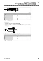
2. Push the coupling hub over the motor shaft, mounting dimension m" (see Fig. 7

and Tab. 3) must be observed.

3. Align the hub and tighten the clamping screws until they have contact.

4. Tighten the clamping screws evenly and crosswise with gradually rising torque

until the indicated tightening torque (see Tab. 3) is reached at all clamping screws.
In the intermediate steps, this procedure should also be repeated until the
indicated tightening torque is reached at all clamping screws.

5. Lay spider in the coupling claw on the gearbox side.

6. Align claws of the motor−side coupling hub with its counterpart.

7. Slowly push on motor, and bolt on to the gearbox flange.

Summary of Contents for g500 Series

Page 1: ...V8i V8i Mounting Instructions EN g500 S130 S660 130 Nm 660 Nm Shaft mounted helical gearboxes shaft mounted helical gearboxes with servo motor...

Page 2: ...Please read these instructions before you start working Follow the enclosed safety instructions 0Abb 0Tab 0...

Page 3: ...earboxes 15 4 3 Preparation 16 4 4 Mounting 16 4 4 1 General information about the assembly of drive systems 16 4 4 2 Mounting the gearboxes 16 4 4 3 Mounting of g500 short servo adapters with clampin...

Page 4: ...Contents i 4 Lenze MA 12 0018 2 0 6 Maintenance 34 6 1 Important notes 34 6 2 Maintenance intervals 34 6 3 Maintenance operations 34 6 4 Repair 40 7 Troubleshooting and fault elimination 41...

Page 5: ...lling mounting commissioning and operating the product Tip Information and tools concerning the Lenze products can be found in the download area at www lenze com 1 1 Document history Material number V...

Page 6: ...dangerous situations Pictograph and signal word Meaning Danger Danger of personal injury through dangerous electrical voltage Reference to an imminent danger that may result in death or serious perso...

Page 7: ...e of protection Surfaces may be hot must not be operated with large vibrations must not be operated in the frequency range of a plant or the drive system All specifications of the corresponding enclos...

Page 8: ...handling neither bend components nor change the insulation distances Electrical installation Carry out the electrical installation according to the relevant regulations e g cable cross sections fusin...

Page 9: ...special protective measures are taken Do not use the integrated brakes as fail safe brakes It cannot be ruled out that the braking torque will be reduced due to disruptive factors that cannot be infl...

Page 10: ...seconds of operation with I IN especially if there is the danger of blocking Installed overload protection does not prevent an overload under any conditions Installed brakes are no fail safe brakes Th...

Page 11: ...l 2 11 Lenze MA 12 0018 2 0 Fire protection Fire hazard Prevent contact with flammable substances 2 5 Disposal Sort individual parts according to their properties Dispose of them as specified by the c...

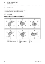
Page 12: ...important technical data is given on the nameplate The product catalogues contain further technical data 3 2 Identification Mounting position A F and position of system modules 1 6 Hollow shaft 0 Wit...

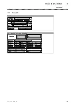
Page 13: ...18 2 0 3 2 1 Nameplate Gearbox 1 3 18 6 5 2 5 3 5 4 7 1 7 2 5 1 10 2 10 3 11 10 1 20 1 L DE 27 38 Asynchronous and synchronous servo motors L 9 15 11 2 4 1 10 2 9 8 1 12 5 5 5 6 5 7 5 8 5 9 14 2 5 2 5...

Page 14: ...8 2 AC DC brake voltage 8 3 Braking torque electrical power input 9 For feedback pulse encoder or resolver data 10 Production data 10 1 Order number 10 2 Material number 10 3 Serial number 11 Bar cod...

Page 15: ...7 G50BS113 g500 S130 15 20 30 G50BS122 g500 S220 20 25 30 40 G50BS140 g500 S400 20 30 35 40 G50BS166 g500 S660 25 35 40 45 Tab 1 Weights in kg Gearbox with motor type MCS Gearbox Motor frame size Code...

Page 16: ...payloads The payload of the hoists and load handling devices must at least correspond to the weight of the load for weights see the catalogue Secure the load so that it will not topple or fall down Wa...

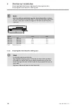
Page 17: ...thread Stop Shocks and blows to the shafts damage the roller bearings 4 4 3 Mounting of g500 short servo adapters with clamping connection Important notes The transmission is made in a force fitting...

Page 18: ...t have cooled down The motor must be deenergised Note Lenze recommends the use of smooth motor shafts without slots 1 Check If the drill depth in the hollow drive shaft is sufficient for the motor sha...

Page 19: ...faces 1 Gearbox degrease 2 Bell housing 3 Motor Mounting 1 Install the gearbox vertically so that the drive end is on top and securely fasten it 2 Locate the position of the mounting hole and remove t...

Page 20: ...erwards insert the wrench 9 into the terminal screw 8 of the clamping ring 7 and leave it there Fig 6 The terminal screw 8 must only be tightened to such a degree that the clamping ring 7 does not mov...

Page 21: ...tightened too much If required loosen it 6 Only when the flange of bell housing 2 and motor 3 lie flat on top of each other the fixing screws may be mounted for the motor screw strength at least 8 8 t...

Page 22: ...D mm max l mm M mm Thread mm Tightening torque Nm Thread mm Tightening torque Nm DIN 6885 1 mm Thread mm Tightening torque Nm 1A 11 23 23 M4 1 5 M3 1 34 M3 1 34 1B 14 40 25 M5 2 0 M6 10 5 B5 x 5 x 16...

Page 23: ...phide or high pressure additives or grease pastes 2 Push the coupling hub over the motor shaft mounting dimension m see Fig 7 and Tab 3 must be observed 3 Align the hub and tighten the clamping screws...

Page 24: ...crosswise and step by step so that the clamping ring is loosened 4 Clean and grease all contact surfaces including threads and head of the clamping screws before reassembly 4 4 5 Attachment of gearbox...

Page 25: ...s dH7 d2 c7 18 20 M6 4 25 30 M10 5 6 35 M12 7 40 M16 8 Tab 4 Dimensions in mm Dismounting 1 Undo axial gearbox locking in the hollow shaft 2 Remove extract the gearbox from the motor shaft using an ap...

Page 26: ...f the machine shaft must be observed Gearbox l1 min l max Code Type G50BS113 g500 S130 89 104 G50BS122 g500 S220 105 120 G50BS140 g500 S400 134 150 G50BS166 g500 S660 150 170 Tab 6 Dimensions in mm 4...

Page 27: ...rial yield point Re 360 MPa E module approx 206 kN mm2 Surface roughness Rz 15 mm 3 Thoroughly clean and degrease hollow shaft bore and machine shaft Note Thoroughly degrease the bore over the entire...

Page 28: ...13 Hollow shaft with shrink disk 3 Outer ring free of grease 4 Inner ring Hollow shaft bore mm 20 25 30 35 40 Clamping screw thread M6 M5 M6 M6 M8 M6 M8 M6 M8 Width across flats SW1 mm 10 8 10 10 13 1...

Page 29: ...nding to the forcing threads in the inner ring For loosening the outer ring screw in the screws evenly to prevent canting Press off the outer ring until loosened completely 4 Remove the drive from the...

Page 30: ...lip the protection cover into the bores 6 x flange side 4 x motor side 4 4 8 Mounting the hoseproof hollow shaft cover 1 3 2 4 3x120 1 Protection cover 3 Reducing bush 2 Cheese head screw 4 Seal 1 Scr...

Page 31: ...e machine housing and then to the gearbox or vice versa The foot can be mounted to the machine using studs or screws not included in the scope of supply Aligning the gearbox with the foot independent...

Page 32: ...be mounted in accordance with the mounting position 35 4 5 Electrical connection Danger Electrical connections must only be carried out by skilled personnel Note The notes for the electrical connecti...

Page 33: ...ve system and avoid any machine movement 5 2 Before switching on Please check Drive function machine function assignment The direction of rotation of the drive shaft g500 S 2 stage g500 S 3 stage Does...

Page 34: ...take special care of changes compared to normal operation like unusual noise stronger vibrations or increased temperatures leakages loose fixing elements the condition of the electrical cables In the...

Page 35: ...he lubricant temperature see Fig 14 Stop With drive systems observe the maintenance intervals for the other drive components A 100 60 1000 10000 50000 70 80 90 110 B C D Fig 14 Lubricant diagram Oil s...

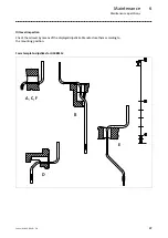
Page 36: ...ze MA 12 0018 2 0 Breather position oil filling screw and drain plug A B G50BS140 G50BS113 G50BS122 G50BS113 G50BS122 C D G50BS113 G50BS140 G50BS166 G50BS122 G50BS140 G50BS166 G50BS113 E F G50BS113 G5...

Page 37: ...ance operations 6 37 Lenze MA 12 0018 2 0 Oil level inspection Check the oil level by means of the displayed dipsticks Manufacture them according to the mounting position Form template dipsticks for G...

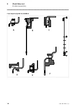
Page 38: ...Maintenance Maintenance operations 6 38 Lenze MA 12 0018 2 0 Form template dipsticks for G50BS122 A B C D E F...

Page 39: ...Maintenance Maintenance operations 6 39 Lenze MA 12 0018 2 0 Form template dipsticks for G50BS140 A B C D E F...

Page 40: ...Maintenance Maintenance operations 6 40 Lenze MA 12 0018 2 0 Form template dipsticks for G50BS166 C B D F A E...

Page 41: ...nds Synthetic oil synthetic hydrocarbon poly alpha olefin oil Fuchs Fuchs Renolin CLP 460 Fuchs Renolin Unisyn CLP 320 Kl ber Kl beroil GEM1 460 N Kl bersynthl GEM4 320 N Kl beroil 4 UH1 220 N Shell S...

Page 42: ...nusual running noises Overload Reduce load Check drive machine assignment Damage to the gearbox or motor Inform Lenze Service Excessive temperature Overload Reduce load Check drive machine assignment...

Page 43: ...Notes 43 Lenze MA 12 0018 2 0...

Page 44: ...63 Hameln Breslauer Stra e 3 32699 Extertal GERMANY HR Lemgo B 6478 49 5154 82 0 49 5154 82 2800 lenze lenze com www lenze com Lenze Service GmbH Breslauer Stra e 3 D 32699 Extertal Germany 0080002446...

Reviews: