background image

Appendix

Parameter set management

Printing parameter sets

10

185

SW-HB 13.0002-EN EN 3.0

10.6.3

Printing parameter sets

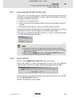
Select the menu items

File

Parameter set

Print

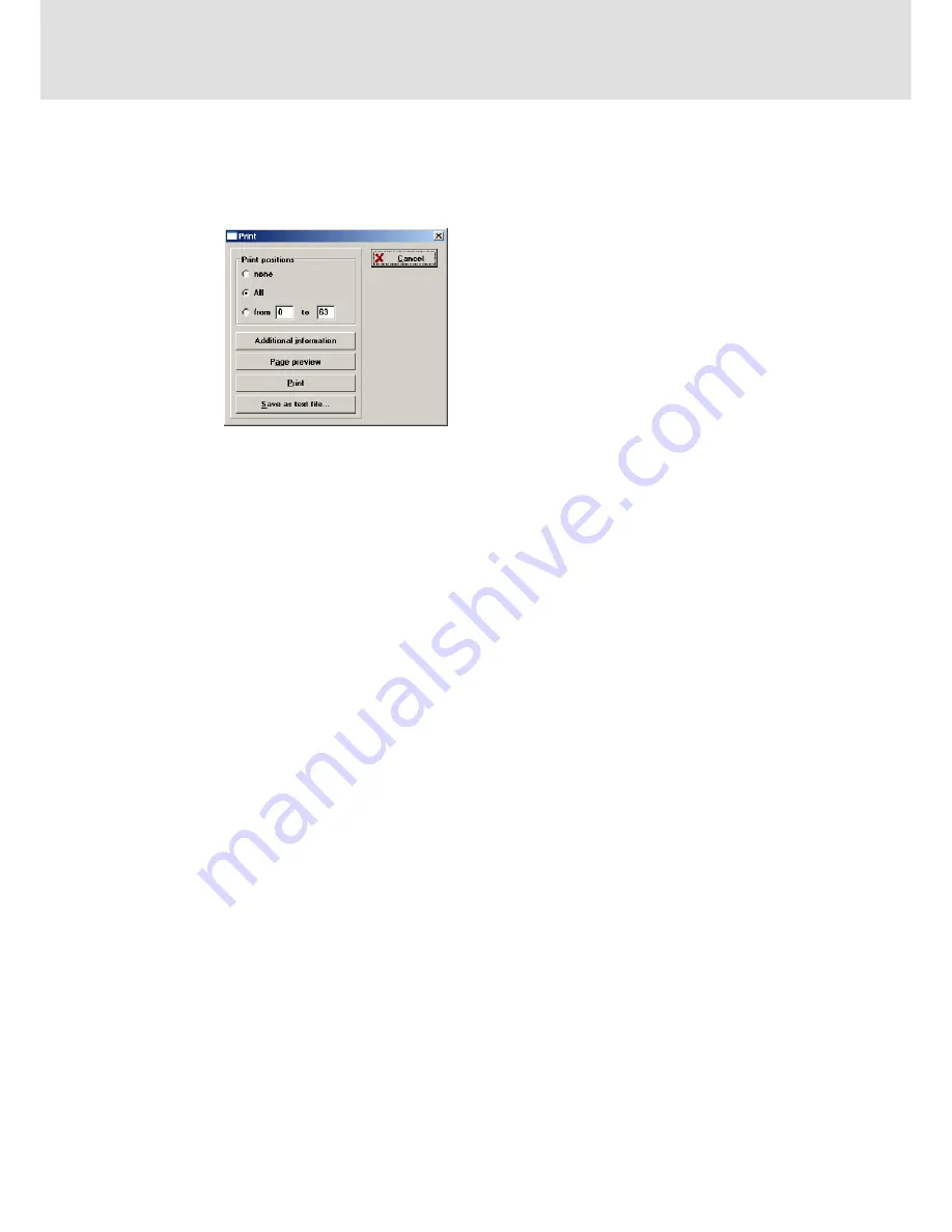
to print, display or save parameter sets

in plain text format: The following menu appears:

931e_340

Inthe

Print positions

field of this menu, you canselect the positions to be printed at the end

of the parameter list.
The selection has the following effects on the plain text output:

ƒ

none
the parameter list will be output without position sets. Approx. 5 pages

ƒ

all
all 64 position sets will be output. Approx. 7 pages

ƒ

from ... to
the position range can be explicitly defined

Meaning of the Print menu buttons:

ƒ

Additional information: Calls the sub-menu of the same name

ƒ

Page preview: Generates the plain text and displays it on the screen

ƒ

Print: Generates the plain text and prints it out.

ƒ

Save as text file: Generates the plain text and saves it under a user-defined name.

The subdirectory \txt is used as default directory for the plain text.

When the plain text for Page preview and Print is created, the file $$$.txt will be written

in the sub-directory \txt.

efesotomasyon.com - Lenze

Summary of Contents for L-force 930

Page 1: ...SW HB 13 0002 EN 0JH Ä 0JHä Software Manual 930 Servo Drives Servo inverter 931E L force efesotomasyon com Lenze ...

Page 2: ...o not accept any responsibility for direct or indirect damage caused e g loss of profit loss of orders or adverse commercial effects of any kind All trade names listed in this documentation are trademarks of their respective owners 2006 Lenze GmbH Co KG Kleinantriebe Hans Lenze Straße 1 D 32699 Extertal No part of this documentation may be reproduced or made accessible to third parties without wri...

Page 3: ... Residual hazards 14 2 5 Definition of notes used 15 3 Installation 16 3 1 Validity information 16 3 2 System requirements 16 3 3 Software installation 17 4 User interface 18 4 1 Building up serial communication 18 4 2 Starting SDC user interface 20 4 2 1 Standard buttons 20 4 2 2 Numerical input fields 21 4 2 3 Control elements 21 4 2 4 Display of setpoints and actual values 22 4 2 5 Standard con...

Page 4: ... 1 Functions available 45 5 3 2 Commissioning steps 47 5 3 3 Selecting a motor from the motor database 48 5 3 4 Activating the operating mode 49 5 3 5 Input configuration 50 5 3 6 Setpoint selection via setpoint selectors 51 5 3 7 Setting the controller enable logic 57 5 3 8 Making the controller ready for operation 58 5 4 Positioning mode 59 5 4 1 Functions available 59 5 4 2 Commissioning steps ...

Page 5: ...96 6 Homing 99 6 1 Parameterisation of homing 104 7 Digital outputs and analog inputs and outputs 107 7 1 Digital outputs DOUT1 DOUT2 107 7 2 Holding brake DOUT3 111 7 3 Analog inputs AIN 113 7 4 Analog outputs AMON 115 8 Using the oscilloscope function 116 8 1 Oscilloscope settings 117 8 2 Oscilloscope window 120 9 Troubleshooting and fault elimination 122 9 1 Error monitorings in the 931E 122 9 ...

Page 6: ...ication interfaces 157 10 2 1 Control via CAN bus 157 10 2 2 Control via the serial interface 160 10 2 3 Control via the technology interface 163 10 3 Serial communication protocol 164 10 4 Communication object list 166 10 4 1 Base units 172 10 4 2 Bit assignment of command word status word error word 173 10 5 Timing charts 177 10 5 1 Switch on sequence 178 10 5 2 Positioning target reached 180 10...

Page 7: ... This Manual addresses to all persons who carry out dimensioning installation commissioning and settings of servo inverters of the 931 series Contents The Product Manual shall ensure safe operation of the Small Drives Control parameterisationprogramforthe931Eservopositioningcontroller The SoftwareManual supplements the Mounting Instructions included in the delivery package ƒ The characteristics an...

Page 8: ...Lenze products can be gathered from the respective catalogs Operating Instructions and Manuals ƒ You can request Lenze documentation from your responsible Lenze sales partner or download it as a PDF file from the Internet 1 2 Terminology used Term In the following text used for Controller 931E servo inverter Device 931E servo inverter Drive 931E servo inverter with connected motor SDC Small Drive ...

Page 9: ...ance of his application with the EC Directives Any other use shall be deemed as inappropriate Liability z The information data and notes in these instructions met the state of the art at the time of printing Claims on modifications referring to controllers which have already been supplied cannot be derived from the information illustrations and descriptions z The specifications processes and circu...

Page 10: ...he drive system that the personnel have the Operating Instructions available for all corresponding operations that non qualified personnel are prohibited from working with and on the drive system Skilled personnel Skilled personnel are persons who because of their education experience instructions and knowledge about corresponding standards and regulations rules for the prevention of accidents and...

Page 11: ...ith the assembly installation commissioning and operation of the product and who have the qualifications required for their occupation Application as directed Drive controllers are components designed for installation into electrical systems or machines They are not household appliances but are only designed as components for industrial or professional purposes in terms of EN 61000 3 2 When instal...

Page 12: ...ufacturer of the system or machine is responsible for the compliance in accordance with the limit values required in connection with EMC legislation Operation Where required systems including controllers must be equipped with additional monitoring and protection devices according to the valid safety regulations e g law on technical equipment regulations for the prevention of accidents The controll...

Page 13: ... be complete In case of questions and problems please contact your Lenze representative ƒ At the time of delivery the communication interfaces meet the state of the art and ensure basically safe operation ƒ The information given in these Operating Instructions refer to the specified hardware and software versions of the modules efesotomasyon com Lenze ...

Page 14: ...rents with regard to low voltage applications current carrying parts can be strongly heated Device protection ƒ Connect or disconnect all pluggable terminals in a deenergised state only ƒ A cyclic connection and disconnection of the supply voltage can overload and destroy the input current limitation of the drive controller When effecting a cyclic switching of the supply voltage over a longer peri...

Page 15: ...h dangerous electrical voltage Reference to an imminent danger that may result in death or serious personal injury if the corresponding measures are not taken Danger Danger of personal injury through a general source of danger Reference to an imminent danger that may result in death or serious personal injury if the corresponding measures are not taken Stop Danger of property damage Reference to a...

Page 16: ...1 ƒ SDC parameterisation software version 2 1 The firmware of the 931E servo positioning controller and the Small Drives Control parameterisation software must match each other i e if a new firmware version with additional functions is used the corresponding version of the Lenze Small Drives Control parameterisation software will be required The Small Drives Control parameterisation software canno...

Page 17: ...k 5 Follow the instructions of the installation program The installation program creates a new program group called Lenze In this program group you can find the entry SDC that is used to start the parameterisation program Note The current version of the Small Drives Control SDC software can be downloaded as installation program from the Lenze web page see www Lenze de If the installation program i...

Page 18: ...Switch on the 931E servo positioning controller 4 Start the parameterisation program If the Online button is highlighted in green in the button menu see figure the communication parameters have been set correctly If the parameterisation program cannot open the serial interface the following error window will appear when the program is started 931e_202 Cause of the error will either be an incorrect...

Page 19: ...fline parameterisation 187 ƒ Firmware download If the servo positioning controller contains an invalid firmware version or if you want to download a new firmware select Firmware download to initiate the firmware download ƒ Exit program Click Exit program to exit the program The below table lists possible error causes and troubleshooting strategies Error Remedy Communication problem Click Retry wit...

Page 20: ...epted and the control window will be closed ƒ Cancel All changes will be undone values that have already been transferred will be restored and the control window will be closed The buttons can be activated ƒ by a click with the left mouse key ƒ with the tab key and confirmation with the ENTER key ƒ via the keyboard by entering the underlined letter while holding down the Alt key If the menu button...

Page 21: ...steps fine adjustment 3 By clicking the fields between grey field and arrow keys The value will change in big steps rough adjustment 4 By clicking the grey field and moving the mouse with the left mouse button being held down Quick value selection in the whole value range rough adjustment 4 2 3 Control elements Graphically oriented control windows are used to lead the users through the program The...

Page 22: ...currently effective in the 931E servo positioning controller A deviation from the setpoint may have different causes Examples Quantisation effects rounding effects etc The modified parameter will only show effect after storage and controller RESET Value range has been temporarily exceeded e g rated current maximum current Incorrect value ranges e g when loading a parameter set from a servo positio...

Page 23: ...s current controller parameters such as current speed etc Select the menu items Display Actual values to configure the actual value window Mark all values to be displayed with a tick Select the options Enable all and Disable all to minimise or maximise the actual value window 931e_366 4 2 6 Directories The installed version of the parameterisation program contains the following sub directories Dir...

Page 24: ...ed fallen below ƒ Faulty data transfer The first two errors are fatal errors that usually do not occur in practical operation In the last case the parameterisation program repeatedly tries to carry out reading writing without bit errors When the value range of a communication object is exceeded fallen below a warning will be displayed If an internal value is available for the object the value will...

Page 25: ...the voltage supply for control section and power stage X2 ƒ Connection of the serial communication cable X1 For additional information please see the Controller Manual GHB931E or the Mounting Instructions Forparametersetting theserial interfaceofthe931E X1 must beconnected with a free COM port on your notebook PC Stop Please carefully check the wiring and the supply voltages selected before switch...

Page 26: ...3 BR 4 24V 5 24V 6 GND 7 GND M 3 KTY X7 X8 X10 24 V DC 24 48 V DC GND Z Z Z 470 470 560 560 RB PES PES PES PES PES PES PE 931E_009 Fig 1 Basic circuit diagram installation according to EMC F1 F2 primary side fusing of the power supply units consider the rules of conductor protection RB external brake resistor PES extensive connection of the shield to PE minimum wiring required for operation S1 rev...

Page 27: ...er with setpoint selection via the analog input AIN0 The controller settings and the current limits have been selected that low that a connected motor of a typical frame size will not be overloaded or destroyed when controller enable is activated by mistake The manufacturer s settings in the default parameter set can be restored via the menu File Parameter set Load default parameter set Note When ...

Page 28: ...illbeconvertedintoanimaginaryand a real part first and then transformed into the rotor coordinates by using the Park transformation Using PI controllers the rotor currents can thus be converted into corresponding rotor voltages and again be inversely transformed into the stator system The driver signal generation uses a symmetrical pulse width modulation for the power stage in sine commutation wit...

Page 29: ... N set point RS232 CAN pos contr Selector velocity controller n_set_pos Set point ramp d dt T n_ist U sin_res U cos_res Resolver Sin Cos Geber U sin_sc U cos_sc phi_mot N act eps_mot velocity filter d dt x act reference run fixed zero Sync RS232 CAN pos contr Selector correcting set point AIN1 RS232 CAN vel contr i_max Selector torque limit i_limit i_max 0 n_limit 0 DIN8 n_limit 0 DIN7 n_max n_max...

Page 30: ...ents 32 7 Open the menu Operating mode Setpoint Selection and select the setpoint source 33 8 Open the menu Parameters Device parameters Controller enable logic and activate the controller enable logic 43 9 Ensure that the controller is inhibited If the controller is only enabled via the digital input DIN9 set the input to LOW DIN9 LOW 10 Switch on the power supply 11 Check if any error messages h...

Page 31: ...tra low voltage version Apart from the motor data pole pair number stator inductance default settings for the feedback system and current and speed controller have been implemented Using the default settings will make commissioning fast and easy ThefunctioncanbeaccessedviathemenuParameters Device parameters Motordata Select new motor A list will be displayed from which you can select the motor use...

Page 32: ... command window as follows 931e_208 5 2 5 Input configuration Select themenuParameters I Os Digitalinputsandcheck iftheanaloginput hasbeen configured correctly Note The analog inputs must not be configured as digital inputs The selection AIN s used as DIN s must not be set otherwise the analog setpoint cannot be evaluated 931e_214 efesotomasyon com Lenze ...

Page 33: ...indicated the digital entries might be activated The following setpoint sources can be selected ƒ 2 analog inputs AIN0 and AIN1 For parameter setting please see the chapter Digital outputs and analog inputs and outputs ƒ Fixed value RS232 ƒ Fixed value CAN ƒ Position controller in operating mode speed control Note If no setpoint source is activated inactive the setpoint will be zero The setpoint m...

Page 34: ...que or Speed setpoint In the Offset field you can select a voltage that will be automatically added to the voltage measured at the analog input This function may for instance be used to compensate for the offset on the analog control voltage of a control and the offset of the analog input in the controller This solves the problem of a very low setpoint still being generated with an external voltag...

Page 35: ...or via the extern control the function safe zero must not be activated because activation will have the same control effects as a dead band or backlash in the controlled system During operation this will lead to a reduced stability of the control circuit This menu contains separate tabs for the analog inputs In this way the inputs can be scaled independently of each other efesotomasyon com Lenze ...

Page 36: ...two values Depending on the direction of rotation the acceleration or deceleration time of the ramp can be parameterised péÉÉÇ Åçåíêçä 931e_216 The 931E servo positioning controller can process speed setpoint jumps in different ways It can transfer the jump without filtering it to the speed controller or calculate a function that will smooth the different setpoints of the speed setpoint selector w...

Page 37: ...n an external control is available The ramps should be selected in a way that ensures that the drive will not exceed the current limitation when accelerating under realistic load conditions When the setpoint ramp is selected correctly the overshooting of the speed controller on reaching the setpoint speed can be considerably reduced compared to operation without setpoint ramp In applications with ...

Page 38: ...on next to the setpoint selector The following window appears j áå 931e_220 The activated RS 232 sources will be marked with a green arrow Here you can enter the setpoints and torque limitation Click the red STOP symbol to stop faulty entries immediately After this the setpoint will be set to 0 and transmitted immediately If the setpoints are not to be transmitted immediately uncheck Transmit imme...

Page 39: ...ted current and maximum current values selected in the Motor data menu The current setpoint will thus always be limited to the lower torque limit value Note Applications requiring torque control in a quadrant i e a torque setting from zero to maximum in one direction of rotation can usually be conveniently implemented with speed control and torque limitation ƒ The torque setpoint is selected via t...

Page 40: ... at the shaft This will lead to an increased temperature rise in the motor For stability reasons select the time constant as low as possible The minimum value will be determined by the measuring noise Typical values for the actual speed filter are 0 6 msec to 2 0 msec The speed controller setting must ensure that the actual speed will only overshoot once The overshoot should be approx 15 above the...

Page 41: ...cilloscope channels to the actual speed raw and the speed setpoint to display the step response of the speed controller Note In general the gain factor and the time constant must not be changed abruptly but only gradually To start with select a comparatively long integral action time between 8 msec and 10 msec and gradually increase the gain Only reduce the integral action time step by step after ...

Page 42: ...rations occur Then slowly increase the time constant until the controller is stable and stiff with setpoint 0 Case 1 Too soft speed controller setting Remedy z Increase the gain factor by 2 to 3 tenth of a point z Reduce the time constant by 1 to 2 msec Case 2 Too hard speed controller setting Remedy z Reduce the gain factor by 2 to 3 tenth of a point z Increase the time constant by 1 to 2 msec Ca...

Page 43: ...e menu for setting the controller enable logic The menu can also be selected via the Commands window For selecting the menu click the button in the Controller enable field 931e_224 Using the combo box you can select the following options ƒ via digital input DIN9 Controller enable via digital input DIN9 ƒ via DIN9 and serial interface For controller enable DIN9 must be set and a corresponding seria...

Page 44: ...ses Repeat the automatic identification See the chapter Motor data 134 The motor shaft vibrates and does not run smoothly The selected angle encoder offset and or controller parameters are not correct See the chapter Speed control 40 Repeat the automatic identification See the chapter Angle encoder 136 The shaft does not rotate z No DC bus voltage z The limit switches are active z Quick stop DIN 6...

Page 45: ...or voltages and again be inversely transformed into the stator system The driver signal generation uses a symmetrical pulse width modulation for the power stage in sine commutation with the 3rd harmonic wave An integrator monitors the current2 time integral of the controller If the maximum value maximum current for 2 sec is exceeded a warning will be sent and the current will be limited to the rat...

Page 46: ...n N set point RS232 CAN pos contr Selector velocity controller n_set_pos Set point ramp d dt T n_ist U sin_res U cos_res Resolver Sin Cos Geber U sin_sc U cos_sc phi_mot N act eps_mot velocity filter d dt x act reference run fixed zero Sync RS232 CAN pos contr Selector correcting set point AIN1 RS232 CAN vel contr i_max Selector torque limit i_limit i_max 0 n_limit 0 DIN8 n_limit 0 DIN7 n_max n_ma...

Page 47: ... Os Digital inputs and check the digital input assignments 50 7 Open the menu Operating mode Setpoint Selection and select the setpoint source 52 8 Open the menu Parameters Device parameters Controller enable logic and activate the controller enable logic 57 9 Ensure that the controller is inhibited If the controller is only enabled via the digital input DIN9 set the input to LOW DIN9 LOW 10 Switc...

Page 48: ...xtra low voltage version Apart from the motor data pole pair number stator inductance default settings for the feedback system and current and speed controller have been implemented Using the default settings will make commissioning fast and easy ThefunctioncanbeaccessedviathemenuParameters Device parameters Motordata Select new motor A list will be displayed from which you can select the motor us...

Page 49: ...rresponding menus will then automatically use the selected unit Ifthetorqueistobeselected inNm thetorqueconstant i e theconversionfactorbetween current and torque must be known The torque constant can be entered in the menu Parameters Deviceparameters Motordata Usually itcanalsobecalculatedbymeans of the nameplate data on the motor For this divide the rated torque by the rated current Note A torqu...

Page 50: ...ation Select themenuParameters I Os Digitalinputsandcheck iftheanaloginput hasbeen configured correctly Note The analog inputs must not be configured as digital inputs The selection AIN s used as DIN s must not be set otherwise the analog setpoint cannot be evaluated 931e_214 efesotomasyon com Lenze ...

Page 51: ...se the setpoint management of the 931E servo positioning controller for setpoint selection Select Operating mode Setpoint selection to open the corresponding menu Whenactivating theTorque controltab oneofthe above mentioned setpoint sources can be selected via Selector Torque setpoint Selector With torque control there is no ramp generator and connecting setpoint efesotomasyon com Lenze ...

Page 52: ...e the chapter Digital outputs and analog inputs and outputs For parameter setting please see the chapter Analog inputs AIN0 and AIN1 ƒ Fixed value RS232 ƒ Fixed value CAN ƒ Speed controller in operating mode torque control Note If no setpoint source is activated inactive the setpoint will be zero The setpoint management manages your settings separately for every operating mode This means that the ...

Page 53: ...que or Speed setpoint In the Offset field you can select a voltage that will be automatically added to the voltage measured at the analog input This function may for instance be used to compensate for the offset on the analog control voltage of a control and the offset of the analog input in the controller This solves the problem of a very low setpoint still being generated with an external voltag...

Page 54: ... or via the extern control the function safe zero must not be activated because activation will have the same control effects as a dead band or backlash in the controlled system During operation this will lead to a reduced stability of the control circuit This menu contains separate tabs for the analog inputs In this way the inputs can be scaled independently of each other efesotomasyon com Lenze ...

Page 55: ...on next to the setpoint selector The following window appears j áå 931e_220 The activated RS 232 sources will be marked with a green arrow Here you can enter the setpoints and torque limitation Click the red STOP symbol to stop faulty entries immediately After this the setpoint will be set to 0 and transmitted immediately If the setpoints are not to be transmitted immediately uncheck Transmit imme...

Page 56: ... by the rated current and maximum current values selected in the Motor data menu The current setpoint will thus always be limited to the lower torque limit value Note Applications requiring torque control in a quadrant i e a torque setting from zero to maximum in one direction of rotation can usually be conveniently implemented with speed control and torque limitation ƒ The torque setpoint is sele...

Page 57: ...e menu for setting the controller enable logic The menu can also be selected via the Commands window For selecting the menu click the button in the Controller enable field 931e_224 Using the combo box you can select the following options ƒ via digital input DIN9 Controller enable via digital input DIN9 ƒ via DIN9 and serial interface For controller enable DIN9 must be set and a corresponding seria...

Page 58: ...ge the motor phases Repeat the automatic identification See the chapter Motor data 134 The motor shaft vibrates and does not run smoothly The selected angle encoder offset and or controller parameters are not correct Repeat the automatic identification See the chapter Angle encoder 136 The shaft does not rotate z No DC bus voltage z The limit switches are active z Quick stop DIN 6 has not been ass...

Page 59: ...ontroller short P controller The current position is calculated from the data of the internal encoder evaluation The position difference is processed by the position controller and transmitted as speed setpoint to the speed controller ƒ The trajectory generator calculates the traversing profile necessary to approach the target position from the current position and with the current speed It provid...

Page 60: ...ng parameters of positioning control fieldbus CAN homing course program Trajectory generator c Positioning parameters d Temp data record Pos set N precontrol Target reached Remaining path message x act Positioning start Following error monitoring Following error Correction speed N set pos Dead range Position controller efesotomasyon com Lenze ...

Page 61: ...d into 4 groups For each of the 4 groups you canset the following parameters ƒ Acceleration ƒ Traversing speed ƒ Type of acceleration Acceleration with jerk limitation or time optimal constant acceleration ƒ Relative or absolute positioning ƒ Waiting until end of current positioning or deletion of current positioning ƒ Start delay In addition there are position sets for positioning via the CAN bus...

Page 62: ...tioning Settings position sets course program and select the positioning range 65 8 Open the menu Parameters Positioning Destination parameters and parameterise the position sets 66 9 Ensure that positioning is inhibited Digital input DIN6 Positioning start must be set to LOW DIN6 LOW 10 Switch on the power supply 11 Check if any error messages have occurred First remove and acknowledge the errors...

Page 63: ...extra low voltage version Apart from the motor data pole pair number stator inductance default settings for the feedback system and current and speed controller have been implemented Using the default settings will make commissioning fast and easy ThefunctioncanbeaccessedviathemenuParameters Device parameters Motordata Select new motor A list will be displayed from which you can select the motor u...

Page 64: ...nctionalities to thedigital inputs DIN0 DIN5 In positioning mode you can specify a 6 bit position selector DIN0 DIN5 to address a target position out of the 64 freely programmable target positions Moreover thestart input is important forpositioning Asanoption it ispossible to derive an offset for the CAN node address from the digital inputs DIN0 DIN5 These twofunctionalitiescan however onlybeused ...

Page 65: ...and Maximum value in the Positioning range field specify the absolute positioning limits for the position setpoint and the actual position The positioning range always refers to the zero position of the drive A click on the Homing run buttonopens theHoming runmenu Seethe chapter Homing 99 A click on the Destination parameters button opens the menu for parameterising the target positions Inthelower...

Page 66: ...ons of the position group 0 to 15 Other parameters of this menu also apply to all 64positions Inthis case theentry 0 63 will followthefield name If thereis no entry after the field name the parameter only applies to the corresponding position As an alternative to the standard position sets 0 63 you can activate the option CAN Bus to display and change the traversing profile currently parameterised...

Page 67: ...cess will be interrupted and the new position will be approached immediately ƒ Ignore start command the new positioning command can only be selected and started when the previous positioning process has been completed Note Please observe that a bouncing switch at the digital start input may lead to problems if wait for end of positioning run or Interrupt actual positioning is selected during a rel...

Page 68: ... for traversing to the target position The final speed is always zero and cannot be parameterised Use the Acceleration field to parameterise the accelerations for accelerating and decelerating the drive The times resulting from running speed and accelerations can be read in the Times field Use the Time constant jerk free field to set the filter time for smoothing the acceleration ramps to reach je...

Page 69: ... optimal positioning and positioning with jerk limitation The positioning range selected under Parameters Positioning Settings position sets course program is shown in the Positioning range input limits field Note The settings of the setpoint ramp do not have any influence on the traversing profiles during homing and positioning efesotomasyon com Lenze ...

Page 70: ...he menu for setting the controller enable logic The menu can also be selected via the Commands window For selecting the menu click the button in the Controller enable field 931e_224 Using the combo box you can select the following options ƒ via digital input DIN9 Controller enable via digital input DIN9 ƒ via DIN9 and serial interface For controller enable DIN9 must be set and a corresponding seri...

Page 71: ...ion For approaching a target position click the corresponding button In addition you can start positioning to the indicated destination by clicking the GO button 931e_240 ƒ Via the digital inputs The individual destinations are selected via the digital inputs DIN0 DIN5 After a rising edge at digital input DIN6 the destinations will be accepted and positioning will be started Inpositioningmode some...

Page 72: ...oints will only be enabled if the limit switch inputs are connected with 24 V limit switches with NC contact If no signal is received the drive will decelerate to speed 0 when the current limit is reached the power stage will remain on DIN7 Negative limit switch DIN6 Positioning start With a rising edge positioning will be executed with the selected parameter set DIN5 Selection of positioning para...

Page 73: ...lternative entry points The entry points can be freely parameterised and are started by means of digital inputs Thus you can use a course program with two entries or alternatively two smaller course programs with up to 32 program steps which can be called completely independently of each other ƒ The course program can be easily created and monitored by using the parameterisation interface The crea...

Page 74: ...ngs position sets course program to select the positioning range and activate Course program active in the Course program field 79 8 Open the menu Parameters Positioning Destination parameters and parameterise the position sets 80 9 Open the menu Parameters Positioning Course program and create the course program 84 10 Ensure that the controller is inhibited If the controller is only enabled via t...

Page 75: ...xtra low voltage version Apart from the motor data pole pair number stator inductance default settings for the feedback system and current and speed controller have been implemented Using the default settings will make commissioning fast and easy ThefunctioncanbeaccessedviathemenuParameters Device parameters Motordata Select new motor A list will be displayed from which you can select the motor us...

Page 76: ...se program Activating the operating mode 5 76 SW HB 13 0002 EN EN 3 0 5 5 4 Activating the operating mode For selecting thecourse programpositioning configurethe command window as follows 931e_242 efesotomasyon com Lenze ...

Page 77: ... EN 3 0 5 5 5 Input configuration In the menu Parameters I Os Digital inputs the two analog inputs must be used as digital inputs 931e_368 Select Functional overview to display the digital inputs available and the current input assignments 931e_246 efesotomasyon com Lenze ...

Page 78: ...m DIN 5 Start 2 Rising edge Traversing to a defined start position Start of course program START1 has priority over START2 if both inputs are switched at the same time DIN 6 Positioning Start Rising edge If DIN 3 Low Start of positioning DIN 7 Limit switch 0 Limit switch 0 DIN 8 Limit switch 1 Limit switch 1 DIN 9 Clear error Controller enable If errors have occurred they can be acknowledged after...

Page 79: ...nd Maximum value in the Positioning range field specify the absolute positioning limits for the position setpoint and the actual position The positioning range always refers to the zero position of the drive A click on the Homing run buttonopens theHoming runmenu Seethe chapter Homing 99 A click on the Destination parameters button opens the menu for parameterising the target positions Inthelowerp...

Page 80: ...ameters of this menu also apply to all 64positions Inthis case theentry 0 63 will followthefield name If thereis no entry after the field name the parameter only applies to the corresponding position As an alternative to the standard position sets 0 63 you can activate the option CAN Bus to display and change the traversing profile currently parameterised via the CAN bus In the Positioning field y...

Page 81: ...on will be approached immediately ƒ Ignore start command the new positioning command can only be selected and started when the previous positioning process has been completed Note Please observe that a bouncing switch at the digital start input may lead to problems if wait for end of positioning run or Interrupt actual positioning is selected during a relative positioning process In this case it m...

Page 82: ...for traversing to the target position The final speed is always zero and cannot be parameterised Use the Acceleration field to parameterise the accelerations for accelerating and decelerating the drive The times resulting from running speed and accelerations can be read in the Times field Use the Time constant jerk free field to set the filter time for smoothing the acceleration ramps to reach jer...

Page 83: ...optimal positioning and positioning with jerk limitation The positioning range selected under Parameters Positioning Settings position sets course program is shown in the Positioning range input limits field Note The settings of the setpoint ramp do not have any influence on the traversing profiles during homing and positioning efesotomasyon com Lenze ...

Page 84: ...rogram that has already been created into theservo positioning controller or click Program File to save the program you have created In the Modus field you can select between the Edit entry mode and the Debug monitoring mode For a detailed description of the monitoring mode please see the chapter Debugging the course program A click on the Editline buttonor a line inthe tableopens anotherwindow in...

Page 85: ...ll be approached ƒ Go to position line immediately The new following position next line X will be approached immediately The current positioning process will be interrupted immediately ƒ Complete positioning then following position line The current positioning process will be completed Then the following position next line X will be approached in accordance with the signal received Basically appli...

Page 86: ...ocess if any will be interrupted The drive will decelerate along the set deceleration ramp As soon as the stop signal changes to HIGH again positioning will be continued ƒ The position branch will not be executed The program will stop in the current program line ƒ The edge evaluation of the signals NEXT1 and NEXT2 will even be continued if the stop signal is active ƒ The outputs DOUT1 and DOUT2 wi...

Page 87: ... will continue execution in the next command line NEXT1 NEXT2 POS A POS B 931E_111 Fig 9 Course program position branch Line N LIne N 1 Neither NEXT1 nor NEXT2 If the digital signal NEXT1 changes to HIGH rising edge position A will be approached If thedigital signal NEXT2changes to HIGH rising edge position Bwill beapproached Ifno rising edges are detected the course program will remain in standby...

Page 88: ...en activated All signal transitions detected since the start of positioning are evaluated If the signal Target reached has been set without detection of a rising signal of NEXT1 2 the program will remain in program step 11 until at least one signal of NEXT1 2 has been detected t1 t2 t3 t4 t5 t6 t7 t8 931E_112 Fig 10 Time chart position branch c Program step 10 d Program step 11 Positioning Target ...

Page 89: ...ignal program execution will continue inlineX Ifthedigital signal NEXT2changes to HIGH rising signal programexecutionwill continue in line Y If no rising signals are detected the course program will remain in standby If neither Evaluate NEXT1 nor Evaluate NEXT2 is set you can select the next line to which the program will jump automatically NEXT1 NEXT2 931E_113 Fig 11 Course program branch line Li...

Page 90: ...uts will be evaluated and the program will jump to the corresponding course program line Next line 1 or 2 depending on whether NEXT1 or NEXT2 has been active first and process it t1 t2 t3 t4 t5 t6 t7 931E_114 Fig 12 Time chart branch line c Program step 10 d Program step 11 e Program step X Y Positioning Target reached NEXT1 2 edge found DOUT1 2 HIGH LOW DOUT1 2 Target reached remaining path Cours...

Page 91: ...nt lines NEXT1 HIGH NEXT1 LOW 931E_115 Fig 13 Course program level test Line N Line X Line Y Neither NEXT1 nor NEXT2 If the digital signal NEXT1 HIGH program execution will continue in line X If the digital signal NEXT1 LOW program execution will continue in line Y For an unconditional program jump e g for never ending loops select the same jump target for NEXT1 HIGH and NEXT1 LOW efesotomasyon co...

Page 92: ...t3 t4 t5 t6 931E_116 Fig 14 Time chart level test c Program step 10 d Program step 11 e Program step 12 DOUT1 2 HIGH LOW DOUT1 2 Target reached remaining path Course program activities t1 DOUT1 2 HIGH LOW program step 10 t2 DOUT1 2 HIGH LOW program step 11 t3 DOUT1 2 HIGH LOW program step 12 t4 Target reached remaining path positioning program step 10 t5 Evaluate level of NEXT1 2 t6 Calculate new ...

Page 93: ...ommand End of Program 931e_256 The current positioning process will be completed then the program will be closed No digital outputs will be set reset No other positioning process will be started If Evaluate stop signal is activated the current positioning process can be interrupted efesotomasyon com Lenze ...

Page 94: ...he menu for setting the controller enable logic The menu can also be selected via the Commands window For selecting the menu click the button in the Controller enable field 931e_224 Using the combo box you can select the following options ƒ via digital input DIN9 Controller enable via digital input DIN9 ƒ via DIN9 and serial interface For controller enable DIN9 must be set and a corresponding seri...

Page 95: ...am is active or being processed ƒ Course program stop Will be on when the course program has been stopped by the stop signal ƒ NEXT1 NEXT2 Indicates the current status of the digital inputs for NEXT1 2 ƒ DOUT1 DOUT2 Indicates the current status of the digital outputs DOUT1 2 ƒ Line Indicates the line currently processed by the course program In the table the line will be highlighted in blue ƒ Posi...

Page 96: ...am Linear linkage of positions Positions 1 2 3 18 are to be approached The drive is to stop for 1 second at every position Then the course program shall stop Pos 1 Pos 2 Pos 3 Pos 18 Start Stop 931E_119 Fig 15 Linear linkage of positions Implementation 931e_260 Implementation ƒ The start delay for positions 1 2 3 and 18 must be parameterised when the target positions are programmed efesotomasyon c...

Page 97: ...OUT1 shall be set to HIGH for one second Pos 1 Pos 2 Pos 3 Pos 18 Start Stop 931E_119 Fig 16 Linear linkage of positions with digital output setting Implementation 931e_262 Implementation ƒ Positions 1 2 3 and 18 are parameterised with a start delay of 1 second ƒ The setting Target reached for DOUT1 must stand in line 3 because the setting On or Off will be accepted immediately and the signal will...

Page 98: ...seconds start delay Pos 16 Start 931E_120 Fig 17 Setting and querying of digital inputs and outputs Query of NEXT1 Implementation 931e_264 Implementation ƒ The following trick is used for a defined setting of DOUT1 Position 0 is set to 0 revolutions relative with a start delay of 1 second First position 0 will be approached and DOUT1 set to HIGH Then the program will jump to line 2 ƒ For a never e...

Page 99: ... to the negative or positive limit switch with or without the zero pulse of the angle encoder ƒ Homing without additional signal to the negative or positive limit stop ƒ Homing to the zero pulse of the angle encoder ƒ No run Homing is started by setting controller enable or via the fieldbus When homing has been completed successfully a status bit will be set in the device The status can be evaluat...

Page 100: ...switch 1 931E_102 Fig 18 Homing to the negative limit switch with zero pulse evaluation Zero pulse Negative limit switch Mode 2 Positive limit switch with zero pulse evaluation With this mode the drive traverses at search speed in positive direction until reaching the positive limit switch In Fig 19 this is indicated by the rising edge Then the drive traverses back at crawl speed and searches for ...

Page 101: ...ck at crawl speed and searches for the exact position of the limit switch The zero position refers to the falling edge of the negative limit switch 17 931E_104 Fig 20 Homing to the negative limit switch Negative limit switch Mode 18 Homing to the positive limit switch With this mode the drive traverses at search speed in positive direction until reaching the positive limit switch In Fig 21 this is...

Page 102: ... pulse evaluation With this mode the drive traverses in negative direction until reaching the limit stop The 931E servo positioning controller needs at least 1 second to detect the limit stop When selecting the limit stop ensure that it will not be damaged when the maximum current parameterised will be applied The zero position refers to the first zero pulse of the angle encoder in positive direct...

Page 103: ...ro pulse of the angle encoder in negative direction from the limit stop 2 931E_108 Fig 24 Homing to the positive limit stop with zero pulse evaluation Zero pulse Mode 17 Homing to the negative limit stop With this mode the drive traverses in negative direction until reaching the limit stop The 931E servo positioning controller needs at least 1 second to detect the limit stop When selecting the lim...

Page 104: ...l components of the positioning axis have been dimensioned accordingly Select the traversing speed as low as possible to limit the kinetic energy when traversing against the limit stop Mode 35 Homing to the current position no run With mode 35 the zero position will be referred to the current position when homing is started 6 1 Parameterisation of homing The homing parameters are selected in the H...

Page 105: ...f the home position itself i e the calculated zero position for the following positioning processes is a certain distance away from the home position of the homing run the distance can be specified in the Offset start position field When the option Go to zero position after homing run is activated the drive will traverse at running speed to the zero position when homing has been completed Note Whe...

Page 106: ...eeds and accelerations for the following actions ƒ Search The drive traverses to the target limit switch limit stop ƒ Crawl The drive reverses at low speed to determine the contact threshold ƒ Running Optional traversing to the zero position home position of the application 931e_268 efesotomasyon com Lenze ...

Page 107: ...ng states of the 931E servo positioning controller The output DOUT0 is firmly connected and indicates if the servo positioning controller is ready for operation The digital output DOUT3 is firmly assigned to the holding brake The digital outputs DOUT1 and DOUT2 can be assigned to different functionalities For an overview of the available digital outputs and the current function assignments please ...

Page 108: ...age ƒ Following error ƒ Remaining path message ƒ Target reached ƒ Homing completed ƒ Comparison speed reached ƒ Course program With some selections there is a button with three points behind the selection box If you click this button a window opens in which you can enter additional settings Setting the messages for the digital outputs When used together with a control it may be useful in many appl...

Page 109: ...ollowing error will be set 931e_320 Note ƒ The following error message should be activated in all positioning applications The ideal size of the tolerance margin depends on many parameters such as controller gain in the speed and position control circuit resolution of the position detection etc ƒ With the Message delay parameter you can increase the ruggedness of the system because not any short t...

Page 110: ... delay in which the actual position must be within the tolerance window before the message Target reached will be set 931e_322 jçíçê ëéÉÉÇ ãÉëë ÖÉ ƒ Declared speed Speed at which the message Declared speed reached will be set ƒ Message window Tolerance margin in which the actual speed must be around the declared speed to ensure that the message Declared speed reached will be set 931e_324 efesotoma...

Page 111: ... holding brakes are subject to switching delays The servo positioning controller considers this during operation Corresponding delay times can be selected see Fig 27 on the next page Select the menu Parameters Device parameters Brake functions to edit the parameters for the holding brake control The below window appears 931e_326 The Run delay tF is used to adapt the holding brake control to its me...

Page 112: ...roller enable Power stage active Holding brake released Speed setpoint Actual speed tF Run delay tA Stop delay Note After controller enable speed setpoints or positioning start commands will only become effective after the run delay With torque control the torque setpoints will be activated deactivated at the time of internal controller enable efesotomasyon com Lenze ...

Page 113: ...eed setpoint In the Offset field you can select a voltage that will be automatically added to the voltage measured at the analog input This function may for instance be used to compensate for the offset on the analog control voltage of a control and the offset of the analog input in the controller This solves the problem of a very low setpoint still being generated with an external voltage selecti...

Page 114: ... via the extern control the function safe zero must not be activated because activation will have the same control effects as a dead band or backlash in the controlled system During operation this will lead to a reduced stability of the control circuit This menu contains separate tabs for the analog inputs In this way the inputs can be scaled independently of each other efesotomasyon com Lenze ...

Page 115: ...displayed by the analog monitor Select the scaling in the Scaling field The units will be automatically adapted when the value to be displayed is changed In the Offset field you can select an offset voltage to display for instance positive and negative values IftheNumericoverflowlimitationboxischecked allcalculatedvaluesthatarehigherthan 10 and lower than 0 V will be limited to these values If the...

Page 116: ...flows and digital states and optimise physical parameters The recorded curves e g step responses can be printed out saved as bitmaps or exported to Microsoft Excel Select the menu items Display Oscilloscope or click the below button to start the oscilloscope Two windows will open the oscilloscope window and the Oscilloscope Settings window efesotomasyon com Lenze ...

Page 117: ...pe settings 931e_270 The Oscilloscope Settings window includes four tabs for more precise settings ƒ Ch1 Selection of the measured value on channel 1 ƒ Ch2 Selection of the measured value on channel 2 ƒ Time base Time base setting ƒ Trigger Trigger setting efesotomasyon com Lenze ...

Page 118: ...e following information is required ƒ The object number of the communication object ƒ The information if the object returns a signed value please check signed ƒ The physical unit of the object ƒ A mask The mask is used to mask individual bits of a communication object and display them Select FFFFFFFF hex for analog values The mask is mainly used to display individual bits of a status word Note The...

Page 119: ... an event Symbol Edge Trigger Rising edge digital trigger Event occurs analog trigger Threshold is exceeded Falling edge digital trigger Event disappears analog trigger Threshold is fallen below Note The trigger mode and thus the oscilloscope will only be active if the RUN STOP checkbox is activated in the oscilloscope window When the transfer window is opened or the parameter set is saved the osc...

Page 120: ...horizontal direction Stops the zoom function Zoom function Help text Activates Excel and generates a worksheet with the measured values of the last measurement Excel must be installed on your PC Prints the oscilloscope window Maximises the oscilloscope window Minimises the oscilloscope window Thick lines in oscilloscope display Thin lines in oscilloscope display Activates the Oscilloscope Settings...

Page 121: ...ion of a trigger event The oscilloscope will start data recording immediately ƒ LED The LED indicates the operating status of the oscilloscope Green LED The oscilloscope is active Red LED The oscilloscope is inactive ƒ RUN STOP checkbox The RUN STOP checkbox is used to activate and deactivate the oscilloscope Activate the checkbox if you want to use the oscilloscope ƒ Status display Thecolourbutto...

Page 122: ...ects short circuits between two motor phases and short circuits at the motor output terminals against the positive reference potential of the DC bus If the error monitoring detects an overcurrent the power stage will be switched off immediately to ensure the short circuit strength of the controller ƒ I2T current monitoring with warning for the controller The 931E servo positioning controller is eq...

Page 123: ...DC bus voltage 9 1 3 Monitoring the logic supply ƒ 24 V over undervoltage monitoring The logic supply of the 931E servo positioning controller is monitored When the logic supply is too high or too low an error message will be activated ƒ Internal operating voltages Allinternaloperatingvoltagessuchasthe3 3 Vsupplyfortheprocessoraremonitored 9 1 4 Monitoring the heatsink temperature ƒ Temperature de...

Page 124: ... 931E servo positioning controller is also equipped with an I2t monitoring to limit the average power loss in the motor Since the power loss in the power electronics and in the motor will in the worst case increase square law with the flowing current the squared current value will be used to measure the power loss When reaching 80 of the maximum integrated measurand a warning parameterisable will ...

Page 125: ...erating mode specific monitoring functions will be activated ƒ Communication Communication via the serial interface and the fieldbus CANopen is monitored 9 1 8 Elapsed time meter The931Eservopositioningcontrollerisequippedwithanelapsedtimemeter UsetheSDC parameterisation software open the menu Info Info and select the Times tab to display the elapsed time meter The current status of the elapsed ti...

Page 126: ...ng Response of drive A Immediate switch off of power stage The motor will coast to standstill H Emergency stop The motor will be decelerated at its current limit to speed zero If a motor holding brake is available it will be applied The power stage will be switched off W Warning The controller will continue operation the power stage will remain switched on The warning can be read via the CAN bus o...

Page 127: ... to the control cabinet housing Are there any other sources of heat near the controller that may increase the ambient temperature of the inverter z Check if the ventilation slots of the controller are polluted or obstructed Clean them if necessary z Optimise the controller settings poor settings will lead to an unnecessary heat generation z Check the resolver position adjustment z Reduce the load ...

Page 128: ...ding overloaded or charred short circuit between winding and housing z Cable short circuit between two phases or phase and shield z Insulation of motor phase connections z 931E fault power stage defective or insulation error insulating foil 15 3220 DC bus undervoltage 1 msec DC bus undervoltage z Check DC bus voltage adapt undervoltage tripping threshold if necessary 16 3210 DC bus overvoltage 1 m...

Page 129: ...e encoder setting are not OK z Check configuration of homing z Change controller parameterisation and angle encoder setting 40 6197 Error Motor and angle encoder identification 5 msec z Homing could not be completed successfully z Controller parameterisation and angle encoder setting are not OK z Check resolver plug connection z Check resolver cable for cable breakage short circuit z Check pin ass...

Page 130: ...ng CAN error code Error No Remedy Cause O W H A Activation time Meaning CAN error code Error No 60 6190 Error in preliminary positioning calculation 5 msec Internal error Please contact the Technical Support 62 6180 Stack overflow 5 msec 63 5581 Checksum error 5 msec 64 6187 Initialisation error 5 msec efesotomasyon com Lenze ...

Page 131: ...tact your Lenze representative if your controller indicates an error number that is not described in the error table and identified as an unknown error in the chapter Error management 133 ƒ These error numbers may have been assigned as part of firmware extensions or customer specific firmware versions including additional monitoring functions efesotomasyon com Lenze ...

Page 132: ...not been identified 2 Error correction Remove the cause of the error in the above example carry out a motor and angle encoder identification 3 Error acknowledgement Click the Clear button in the error window If the error has been removed successfully the window will be minimised If the error has not been removed successfully the window will appear again Error acknowledgement is also possible by ac...

Page 133: ...ontrolled stop the motor will be controlled and decelerated to standstill 3 A warning will be indicated the error window will open automatically 4 A warning will be indicated i e a warning will be entered into the error window but the error window will not be opened automatically Some errors are so severe that the user must not demote them to warnings or a certain response is inevitable In these c...

Page 134: ...enu must be activated if the motor could not be identified by means of the list Select the menu Parameters Device parameters Motor data 931e_206 _ ëáÅ é ê ãÉíÉêë Use this menu to enter the maximum and the rated motor current The data can be obtained from the nameplate The torque constant results from the quotient of rated torque rated current efesotomasyon com Lenze ...

Page 135: ...Click Power stage to set the clock frequency For more information please see the chapter Power stage 143 Inaddition youcanenterthepolepairnumberofthemotor Or youcanusetheautomatic identificationroutinewhichautomaticallydeterminesthepolepairnumberandtheoffset angle of the angle encoder For this simply click the Auto detect button Stop Before starting the motor identification ensure that the current...

Page 136: ...ng on the selected angle encoder the menu may differ from the above example menu because different setting options are used Motor and angle encoder can be identified automatically or manually We recommend an automatic adjustment if the motor has not yet been integrated into a system and the axis can be freely moved The function can be activated via the following menus ƒ Parameters Device parameter...

Page 137: ...le encoder left right The following conditions must be met for an automatic identification ƒ The motor is completely wired ƒ The DC bus voltage is available ƒ The servo positioning controller does not indicate any errors red LED blinking ƒ The shaft can be freely moved Stop Before starting the motor identification ensure that the current limits menu items Parameters Device parameters Motor data ha...

Page 138: ...ge is fallen below The manual determination of the angle encoder data requires a profound knowledge of synchronous machines and the encoder used For this reason we recommend to contact your Lenze representative in this case Danger Faulty angle encoder data may lead to uncontrolled motions of the drive which may cause material damage at the motor or the entire system Inadditiontotheangleencodersett...

Page 139: ...cteristics in the menu Parameters Device parameters Motor data see the chapter Motor data 134 Stop Be careful when activating the feedback via the motor e m f With feedback via the motor e m f the real motor speed may significantly deviate from the setpoint if the function and the motor data have not been parameterised correctly The tolerances of the magnets and windings of the motors in the serie...

Page 140: ...The controller feeds the sensor with a measured current A voltage drop at the sensor will be detected and an overtemperature error activated as a result For in sections linear analog temperature sensors it is necessary to select the temperature threshold When the analog temperature sensor is activated enter the corresponding settings in the analog motor temperature field Use the selection field to...

Page 141: ... g due to wrong parameter setting the power stage will be switched off after this time the motor will coast to standstill unless it has already been decelerated to zero ƒ Speed limitation The speed setpoint will be limited to the set value ƒ Torque limitation Click Settings to open the Motor data window For more information please see the chapter Motor data 134 Enter the limit value Maximum curren...

Page 142: ...n this way you can directly see the limit switch assignment to the traversing direction and can adapt the wiring of the limit switches if necessary As long as a limit switch is active the setpoint in the corresponding direction of rotation willbeinhibited Inapplications inwhichalimitswitchoverrunorbouncinglimitswitches are possible we recommend to activate the option Limit switch inhibits directio...

Page 143: ... the motor losses will be slightly reduced in return the losses in the 931E servo positioning controller will increase This is why the maximum current limits are slightly lower The clock frequency selection has no influence on the control behaviour The clock frequency of the power stage is default set to 10 kHz 931e_288 Stop ƒ The settings can only be changed when the power stage is switched off F...

Page 144: ...ameters Device parameters DC bus monitoring to activate the menu 931e_292 The Rated DC bus voltage field indicates the voltage the power stage has been designed for This value cannot be changed Use the Undervoltage detection field to select the response threshold below which the voltage must fall before the controller will detect an undervoltage Depending on the power supply unit useful values are...

Page 145: ...nets in the motor are demagnetised For this reason the current limits specified by the manufacturer must not be exceeded See the chapter Motor data 134 Note When selecting a motor from the motor database you can use optimised current controller settings In this case the current controller settings need not be changed The oscilloscope function can be used to optimise the current controller For more...

Page 146: ...Appendix Parameterisation of outside motors Current controller 10 146 SW HB 13 0002 EN EN 3 0 Fig 29 Step response of the current controller efesotomasyon com Lenze ...

Page 147: ...oller to open the window for the parameterisation of the position controller 931e_298 Enter the following values ƒ Gain Enter the proportional controller gain ƒ Max correction speed Here you can select the maximum speed to be added to the traversing speed in case of a deviation between setpoint and actual position The value should be limited to approx 500 rev min ƒ Dead range Here you can enter a ...

Page 148: ...ation maximum possible value 3 Select the menu items Display Oscilloscope to start the oscilloscope See the chapter Using the oscilloscope function 116 Select the following values Channel 1 Actual speed scaling 1000 rev min div 2 div Channel 2 Rotor position scaling 50 div offset 1 div Time base 100 msec div delay 200 msec Trigger Source actual speed level half the traversing speed mode normal fal...

Page 149: ... common drive configuration 931e_300 Use the Application field to select if your application is a rotary motion or a translatory motion application If you want to select the output unit for your application click the button in the Gearbox field or the Settings button After this the menu Display units will appear For more information please see the chapter Display unit settings 150 Application exam...

Page 150: ...display units are only used for the display in the parameterisation program The parameterisation program communicates with the controller via communication objects in a defined physical base unit Every access via the RS232 interface is made in these base units aáëéä ó ìåáíë The user can select display units for the following physical values ƒ Position revolutions ƒ Speed ƒ Acceleration ƒ Torque in...

Page 151: ...es For linear axes Positions in distance units speed in distance units sec acceleration in distance units sec For rotary drives Positions in revolutions degrees or radian different speed and acceleration units User defined Examples z For linear axes and non metric distance speed and acceleration units e g inch inch min z For rotary drives with special distance speed and acceleration units Direct i...

Page 152: ... For further information please see the chapter Extended options in the menu display units 153 Stop For experienced users only In the Direct input tab the factor group cab be directly written if the selection Direct input is selected The following question appears when the menu is exited 931e_304 Note The input limits are automatically adapted to the physical units set To be on the safe side you c...

Page 153: ... enter the position in inch Enter 1 76 under Feed constant Furthermore you can use the Time base speed and Time base acceleration input fields Use the Time base speed field to define your own speed units Example rotary operation You have a drive with 20 mm per revolution without gearbox and want to enter the speed in mm minute Enter 20 under Feed constant and 60 under Time base speed 60 seconds 1 ...

Page 154: ...EN EN 3 0 aÉÅáã ä éä ÅÉë Furthermore you can select the decimal positions for the display units Go to the Decimal places tab and select the menu Options Display units to select the number of decimal positions for the distance speed and acceleration unit between 0 and 5 931e_308 efesotomasyon com Lenze ...

Page 155: ... the Position Speed and Acceleration factor group in the Direct input tab Stop For experienced users only Through the direct entry of the physical units you can radically change the control parameters of the 931E servo positioning controller You can select the following units for the display of the parameter setting program ƒ Increments ƒ Degrees ƒ Radians ƒ Revolution ƒ Metres ƒ Millimetres ƒ Mic...

Page 156: ...r your application The program uses your entries for the input field limits Note ƒ The input limits can be changed later They will however only have an effect on the input fields of the parameter setting program ƒ The speed and acceleration values in the drive will not be physically limited Use the menu Safety parameters to limit the values in the drive For more information please see the chapter ...

Page 157: ...position selection interpolated position mode The following access types are supported for data exchange Access type Description SDO Service Data Object Used for the standard parameterisation of the controller Approx 150 SDOs are supported PDO Process Data Object Fast exchange of process data e g actual speed possible 2 PDOs are supported SYNC Synchronisation Message Synchronisation of several CAN...

Page 158: ...s more frequently than every 4 msec Otherwise they might not be registered or evaluated by the 931E servo positioning controller This may lead to control jumps or motor jerks ƒ In the worst case a PDO will only become effective in the controller after 4 8 msec e g as a speed setpoint This may be the case if two time slices are required for PDO processing and the control sends the PDO directly afte...

Page 159: ... InaCANopen network all node numbers may only be assigned once ƒ Adding DIN0 DIN3 to the node number The value of the digital inputs DIN0 DIN3 is added to the basic node number The inputcombinationisonlyreadwhentheCANopeninterfaceisactivatedorafterareset of the 931E servo positioning controller Inthisway itispossibletoassignupto16differentdevicenumbersatthedigitalinputs through simple bridges afte...

Page 160: ...ter Communication object list 166 contains a list of all communication objects supported ƒ The controller internal parameter value may slightly differ from the set value because the servo positioning controller internally uses different units and normalisations than the communication objects Serial communication of the SDCparameterisation program The parameterisation program communicates with the ...

Page 161: ...ommunication with the selected baud rate The preferred baud rate will be accepted or reduced to a lower baud rate The implemented baud rate will be indicated as Actual data transfer rate This baud rate is used for the standard online communication withthe servopositioning controller For the firmware download a separate baud rate will be selected Open the menu Options Communication COM port to sele...

Page 162: ...he Transfer window is active other open windows will not be refreshed e g actual values oscilloscope Therefore close the Transfer window when it is no longer required In general the Transfer window is only used to transfer commands that are not of interest for standard operation In addition memory locations and communication objects can be read and written This is as well only necessary in special...

Page 163: ...munication via the serial interface The window is mainly designed for debugging purposes This option is not of interest for standard users 931e_338 10 2 3 Control via the technology interface The 931E servo positioning controller has a technology interface which is equipped with a synchronous serial interface This enables the integration of customer specific extension modules communication interfa...

Page 164: ...R FFFF FFFF Response usually 32 bits If an error occurs the command and an error code will be sent Read internal value OI NNNN NNNN DDDDDDDD or OI FFFF FFFF Read minimum value ON NNNN NNNN DDDDDDDD or ON FFFF FFFF Read maximum value OX NNNN NNNN DDDDDDDD or OX FFFF FFFF Letter Meaning hexadecimal NNNN Communication object number DD D Data bytes FF F Error code 0x00000002 Data value too low not wri...

Page 165: ...e Activate HW reset SQT xxxx CQT Clear history buffer SAVE DONE Save parameter set in FLASH SEP DONE Load parameter set from FLASH TYPE TYPE dddd Type check VERSION xxxx VERSION dddd Version check iiiiss dd iiiiss dd Simulation SDO write access iiiiss iiiiss dd Simulation SDO read access ERROR Unknown command error Letter Meaning hexadecimal xxxx Status message dddd Data bytes nn Node number bbbb ...

Page 166: ...main Main and sub revision number of firmware of version management system Upper 16 bit Main revision Lower 16 bit Sub revision 0018 srvc_custom_main Customer application number sub revision number Upper 16 bit Main revision Lower 16 bit Sub revision 0019 main_bootloader_version Main and sub revision of boot loader Upper 16 bit Main revision Lower 16 bit Sub revision 001A srvc_motid_ctrl Control w...

Page 167: ...E rs232_unit_a_numerator Factor group of acceleration numerator None 005F rs232_unit_a_divisor Factor group of acceleration denominator None 0060 rs232_unit_a_decimals Decimal positions of acceleration None 0061 rs232_kommando Command word None 0062 rs232_osc_screen_time Total time Base unit time 0063 rs232_display_free_adr Free CO address CO number of free CO 0070 errh_err_field_0 Bit field of ma...

Page 168: ...ration word None 00A2 emu_ctrl Operating mode selection None 00A3 eeval_enc_phi_offs Offset angle of angle encoder one rev Base unit degrees 00A4 eeval_x2b_line_cnt Increments of analog incremental encoder Increments 4 x number of increments 00A5 emu_enc_line_cnt Output increments of encoder emulation Increments 4 x number of increments 32 1024 00A6 emu_enc_offset Offset between setpoint angle and...

Page 169: ...ctual speed filtered for display in D2SC Base unit speed 00E3 spdc_n_ref_rs232 Setpoint speed RS232 Base unit speed 00E4 spdc_n_ref_can Setpoint speed CAN Base unit speed 00E5 spdc_n_ref_ftd Setpoint speed FTD Base unit speed 00E6 spdc_n_ref_profi Setpoint speed Profi Base unit speed 00E7 spdc_n_ref_hilf_rs232 Auxiliary speed RS232 Base unit speed 00E8 spdc_n_ref_hilf_can Auxiliary speed CAN Base ...

Page 170: ...on controller Base unit speed 0118 pos_sel_parameter Position controller setpoint selector None 0119 posc_x_diff_time Time to following error activation Base unit time 011A posc_x_diff_lim_pos Following error position difference between setpoint actual value Base unit position 011B posc_x_dead_rng_pos Dead band of position difference Base unit position 011C ipo_sw_lim_pos Position limit of positiv...

Page 171: ...ion setpoint and actual position Base unit position 0138 pos_sel2_x_switch Position controller selector for position setpoint None 0139 pos_sel2_n_switch Setpoint selector for speed precontrol None 0140 can_node_id Node number resulting from base and offset 1 127 0141 can_node_id_offset Node number offset through digital inputs 0 63 0142 can_node_id_base Base node number for CAN 0 127 0143 can_bau...

Page 172: ... address CO number of free CO 016E osc_KO_mask1 Optional mask for hiding non required bits or value ranges in a communication object None 016F osc_data2 Function number for channel recording None 0170 osc_KO_nr2 Free CO address CO number of free CO 0171 osc_KO_mask2 Optional mask for hiding non required bits or value ranges in a communication object None 0190 ftd_pointer_course_prog Pointer to an ...

Page 173: ...ion setpoints if torque control is activated also inverts the torque setpoints 16 Error acknowledgement 18 Setpoint inhibit activated inside the controller 17 Direction bit 0 CCW rotation 1 CW rotation inverts both speed setpoints and position setpoints if torque control is activated also inverts the torque setpoints 16 Error acknowledgement 15 13 12 Start positioning or homing 11 10 Reversal of d...

Page 174: ...s switched on 13 Speed message n_act 0 n_mess_hyst 12 SinCos encoder activated 11 iit monitoring à limitation to rated current IIT motor servo 10 Positioning has been started activated for one IPO cycle 9 Speed message n_act n_set n_mess_hyst 8 1 speed message n_act n_mess n_mess_hyst 7 6 Remaining path positioning reached reset to zero when the following positioning process is started 5 Target re...

Page 175: ...ontroller I t with 100 18 I t error motor I t with 100 17 16 SINCOS track signal error 15 DC bus overvoltage 14 DC bus undervoltage 13 DC bus power stage overcurrent 12 Offset current measurement error 11 10 24V supply error out of range 9 12V electronic supply error 8 5V electronic supply error 7 Resolver track signal error carrier failure 6 SINCOS track signal error 5 SINCOS RS485 communication ...

Page 176: ...rror 30 Checksum error 29 Stack overflow 28 27 Error in preliminary pos calculation 26 25 Operating mode error 24 Position data record error 23 RS232 communication error 22 CAN communication error 21 12 11 Course program jump target error 10 Course program error unknown command 9 8 7 Motor identification error 6 4 3 Homing error 2 Time out with quick stop 1 0 efesotomasyon com Lenze ...

Page 177: ... a tolerance of 100 μsec This tolerance must be considered in addition to the times indicated in the timing diagrams The931Eservopositioningcontrollerisequippedwithasequencecontrolwithatimebase of 1 6 msec The digital input and output states are cyclically detected and updated The cycle time of the PLC or control must be selected 1 6 msec 100 μsec 1 5 msec to ensure that the PLC can detect all mes...

Page 178: ...SW HB 13 0002 EN EN 3 0 10 5 1 Switch on sequence t1 t2 t3 t4 t5 t6 t7 t t t t t t t 931E_121 Fig 31 Switch on sequence Power on DOUT0 Ready Controller enable Power stage is on Holding brake released Speed setpoint Actual speed efesotomasyon com Lenze ...

Page 179: ... of application ƒ t2 1 6 msec ƒ t3 10 msec Depends on the operating mode and the status of the drive ƒ t4 N x 1 6 msec Parameterisable brake parameter for run delay tF ƒ t5 1 6 msec ƒ t6 N x 0 2 msec Depends on the quick stop ramp ƒ t7 N x 1 6 msec Parameterisable brake parameter for stop delay tA efesotomasyon com Lenze ...

Page 180: ...rget reached Positioning start DIN0 DIN5 Positioning in progress DOUT Target reached Set position Actual position ƒ t1 1 6 msec Pulse time of the START signal ƒ t2 1 6 msec Delay until the drive starts ƒ t3 N x 1 6 msec Target window reached message delay ƒ t4 1 6 msec Setup time for position selection ƒ t5 1 6 msec Hold time for position selection efesotomasyon com Lenze ...

Page 181: ...t1 t2 n t t t1 t2 931E_123 Fig 33 Speed message Setpoint speed Actual speed DOUT Setpoint speed reached ƒ t1 1 6 msec ƒ t2 1 6 msec 10 5 4 Error acknowledgement t1 t t t 931E_124 Fig 34 Error acknowledgement Controller enable DOUT Ready DOUT Error ƒ t1 approx 10 msec efesotomasyon com Lenze ...

Page 182: ...active Actual speed 1 Actual speed 2 ƒ t1 0 2 msec ƒ t2 N x 0 2 msec Depends on the quick stop ramp ƒ t3 0 2 msec ƒ t4 N x 0 2 msec Depends on the speed ramp Actual speed 1 Direction of rotation permanently inhibited through the limit switch Actual speed 2 Direction of rotation not permanently inhibited through the limit switch efesotomasyon com Lenze ...

Page 183: ...istics will be referred to as parameters the total of all parameters for a servo positioning controller motor combination will be referred to as parameter set The below figure describes the parameter set management 931E_126 Fig 36 Online parameterisation PC DCO file Small Drive Control SDC Reading from file and saving in servo Reading from servo and saving in file Serial communication Servo contro...

Page 184: ...id basis Select the menu items File Parameter set Load default parameter set to activate the standard parameter set After this the default parameter set will be copied into the FLASH and the RAM 10 6 2 Loading and saving of parameter sets It is possible to save and manage parameter sets externally e g on hard disk floppy disk etc For this the 931E servo positioning controller reads the parameter s...

Page 185: ...utput without position sets Approx 5 pages ƒ all all 64 position sets will be output Approx 7 pages ƒ from to the position range can be explicitly defined Meaning of the Print menu buttons ƒ Additional information Calls the sub menu of the same name ƒ Page preview Generates the plain text and displays it on the screen ƒ Print Generates the plain text and prints it out ƒ Save as text file Generates...

Page 186: ...from file motor ini Due to the format the entries should not be longer than half a line approx 40 characters By default the current date will be used as date for the plain text Click Change to edit the date field and change the date The changed date will be taken over in the plain text Page preview After selecting the Page preview button from the Print menu the plain text will be created and the p...

Page 187: ... sets 185 The changes will only become effective if the modified parameter set is loaded into the 931E servo positioning controller See the chapter Loading and saving of parameter sets 184 The below figure shows the principle of the offline parameterisation 931E_127 Fig 37 Offline parameterisation PC DCO file Small Drive Control SDC Select the menu items Options Communication Offline parameterisat...

Page 188: ...download are locked ƒ The menu File Parameter set has different sub menus Open file Save file Save file as ƒ When exiting the program you will be asked if the parameter file is to be saved Select the menu items Options Communication Online parameterisation or click the online icon in the toolbar to exit the offline parameterisation efesotomasyon com Lenze ...

Page 189: ...Info Info to display general information about the SDC parameterisation tool and the 931E servo positioning controller The following window will appear 931e_344 Note In case of a complaint it will be useful to have the information of these tabs available efesotomasyon com Lenze ...

Page 190: ...e toolbar below the menu bar Commands and functions German language English language French language Find communication Online parameterisation Offline parameterisation Oscilloscope Motor data menu Current controller Speed controller Position controller Homing Select positions Approach positions Save parameters Reset servo positioning controller efesotomasyon com Lenze ...

Page 191: ...mware version If the 931E servo positioning controller contains no or only an incomplete firmware version the following window will appear 931e_356 Note ƒ If the correct firmware is already available in the 931E servo positioning controller the error message will not be displayed In this case the following chapter may be skipped ƒ Select the menu Info Info and open the Firmware hardware tab to rea...

Page 192: ...h you can select the baud rate 931e_350 3 First of all try a baud rate of 115200 baud In the event of data transfer problems error messages reduce the baud rate in the next try If the firmware download has been successful the below message will be indicated 931e_352 If the firmware download has not been successful the message Error at firmware download will be indicated 931e_358 efesotomasyon com ...

Page 193: ...te Firmware download 10 193 SW HB 13 0002 EN EN 3 0 In general the error is due to a communication error during the data transfer to the 931E servo positioning controller Repeat the above procedure with a lower baud rate 931e_354 efesotomasyon com Lenze ...

Page 194: ... 25 Communication settings 161 Communication via communication objects 24 Communication window for RS232 transfer 163 Communication with RS232 161 Control elements 21 Controller application as directed 9 labelling 9 Controller cascade 28 45 Course program 73 digital inputs 73 global settings 65 79 program creation 84 Current controller manual setting 145 D DC bus monitoring 144 Default parameter s...

Page 195: ...files offline parameterisation 187 Loading of parameter sets 184 Loading the DCO file online parameter setting 184 M manual angle encoder data 136 Manufacturer 9 Messages digital outputs 108 following error 147 remaining path 67 81 Motor data 134 automatic determination 134 manual setting 134 Motor protection 14 N Notes definition 15 Numerical input fields 21 O OK 20 Operator 10 Optimation current...

Page 196: ... Retry with old parameters 19 Search Baud rates 19 Setpoint ramp 36 Setpoint sources 33 51 Setpoints 33 51 Settings digital outputs 108 Speed control 28 Speed controller manual setting 40 Speed limitation 141 Start signal digital inputs 64 T Target parameterisation 66 80 Target values 22 Temperature monitoring 140 Toolbar offline online parameterisation 187 online offline parameterisation 187 quic...

Page 197: ...Notes 197 SW HB 13 0002 EN EN 3 0 efesotomasyon com Lenze ...

Page 198: ...Notes 198 SW HB 13 0002 EN EN 3 0 efesotomasyon com Lenze ...

Page 199: ...Straße 1 D 32699 Extertal Germany SW HB 13 0002 EN EN 3 0 09 2006 TD11 49 0 51 54 82 0 Service 00 80 00 24 4 68 77 24 h helpline Service 49 0 51 54 82 1112 E Mail Lenze Lenze de Internet www Lenze com 10 9 8 7 6 5 4 3 2 1 efesotomasyon com Lenze ...

Reviews: