background image

Mechanical installation

Important notes

Install the product according to the information in the chapter "Standards and operating

conditions".

4

Standards and operating conditions


^

 28

The technical data and the data regarding the supply conditions can be found on the

nameplate and in this documentation.

Ambient media − especially chemically aggressive ones − may damage shaft sealing rings,

lacquers and plastics.

Lenze offers special surface and corrosion protection in this case.
 

Preparation

Protect shaft sealing rings from contact with solvents.

Remove protection covers from shafts.

Thoroughly remove anticorrosion agents from the shaft and from flange faces.

Draw the transmission elements onto the output shaft only by using the centering thread.

Align the output shaft and transmission elements exactly to avoid tensions.

Mount belt pulleys, sprockets, or gear wheels as close as possible to the shaft shoulder in

order to keep the bending load of the shaft and the bearing forces at a minimum level.

Tighten all screw connections with the specified torques and secure them with standard

screw locking adhesive.

Check paint for damage and repair professionally.

Installation

The mounting surfaces must be plane, torsionally rigid and free from vibrations.

The mounting areas must be suited to absorb the forces and torques generated during

operation.

Ensure an unhindered ventilation.

For versions with a fan, keep a minimum distance of 10 % from the outside diameter of the

fan cover in intake direction.

Dimensions

Dimensions are contained in the configuration document.

Mechanical installation

Important notes

14

Summary of Contents for MQA 20

Page 1: ...Servo motors MQA asynchronous servo motor Mounting and switch on instructions EN...

Page 2: ......

Page 3: ...Mounting 15 Electrical installation 16 Important notes 16 Preparation 16 Motor connection 17 Connection via terminal box 17 Connection via ICN connector 19 Commissioning 24 Important notes 24 Before...

Page 4: ...her with the complete documentation of the product For safety rated attachments observe the enclosed operating instructions of the manufacturer The document includes safety instructions which must be...

Page 5: ...er documentation with additional information Example EDKxxx see documentation EDKxxx Layout of the safety instructions DANGER Indicates an extremely hazardous situation Failure to comply with this ins...

Page 6: ...take responsibility for the suitability of the process and circuit proposals All work with and on the product may only be carried out by qualified personnel IEC 60364 and CENELEC HD 384 define the qua...

Page 7: ...e drive components e g capacitive caused by inverter supply Careful earthing in the marked positions of the components must be carried out There is a risk of burns from hot surfaces Provide protection...

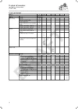
Page 8: ...power HP 5 10 Continuous standstill torque 5 11 Power factor cos 8 Brake data Type supply voltage electrical power consumption braking torque 9 Feedback 10 Production data 10 2 Material number 10 3 S...

Page 9: ...at AM32 5V E EQI SinCos absolute value encoder multi turn EnDat AM2048 5V E EQN Resolver RS0 Safety resolver RV03 RV0 SinCos safety incremental encoder single turn IG1024 5V V3 S1S SinCos incremental...

Page 10: ...phase AC motors 1 Number of pole pairs for resolvers 2 3 4 Number of bits steps or increments per revolution 20 32 128 512 1024 2048 Supply voltage 5 V 8 V 15 V 24 V Interface or signal level Standar...

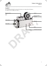
Page 11: ...ents and connections on the product Their position size and appearance may vary Brake Motor connection Feedback Temperature monitoring Output flange Output shaft Motor connection Power Brake Cooling F...

Page 12: ...olts or support plates Do not damage any components during transport Avoid electrostatic discharges on electronic components and contacts Avoid impacts Check the carrying capacity of the hoists and lo...

Page 13: ...sible in the manufacturer s packaging In dry low vibration environment without aggressive atmosphere Protect against dust and impacts Observe the climatic conditions according to the technical data 4E...

Page 14: ...shaft only by using the centering thread Align the output shaft and transmission elements exactly to avoid tensions Mount belt pulleys sprockets or gear wheels as close as possible to the shaft shoul...

Page 15: ...distortion Compensate minor inaccuracies by suitable flexible couplings Fastening Use screws with a minimum property class of 8 8 Observe prescribed tightening torques Secure against unintended loose...

Page 16: ...e system or machine is responsible for adherence to the limits required in connection with EMC legislation Operation on an external inverter A max pulse voltage amplitude of Upk 1560 V at the motor te...

Page 17: ...irmly tightened The terminal box has to be free of foreign bodies dirt and humidity All unused cable entries and the terminal box itself must be sealed so that they are dust tight and waterproof The s...

Page 18: ...terminal Threaded bolt Stripping length mm 18 20 18 Threaded bolt M12 Tightening torque Nm 3 2 15 5 Terminal box power Contact Name Meaning U1 L1 Motor winding phase V1 L2 W1 L3 PE PE PE conductor Ter...

Page 19: ...the connections 1 3 2 Position Meaning 1 Power connection Brake connection PE connection 2 Feedback connection Connection of temperature monitoring 3 Blower connection Electrical installation Motor co...

Page 20: ...ent 8 pole 1 2 W U V ICN M40 8 pole Contact Name Meaning BD1 Holding brake BD2 Holding brake PE PE PE conductor U U Power phase U V V Power phase V W W Power phase W 1 Not assigned 2 Not assigned Elec...

Page 21: ...ed 10 Schirm Encoder housing shield 11 Temperature monitoring PT1000 12 Temperature monitoring PT1000 ICN M23 connector assignment Incremental and SinCos absolute value encoder Hiperface 1 2 3 4 5 6 7...

Page 22: ...ot assigned 4 0 V Sensor 0 V sensor 5 PT1000 KTY temperature sensor 6 PT1000 KTY temperature sensor 7 UB Supply 8 Takt EnDat interface cycle 9 Takt Inverse EnDat interface cycle 10 GND Mass 11 Schirm...

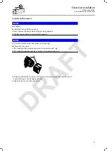
Page 23: ...class due to incorrect mounting Malfunctions may occur ICN connector with screwed connection Do not remove O ring ICN connector with bayonet lock remove O ring and dispose of it 1 1 When connecting th...

Page 24: ...ence of the motor connection correct Is the contact of good electrical conductivity if a PE connection on the motor housing is used After a long period of downtime or after overhauling the motor check...

Page 25: ...ly If equipped with blower clean the air inlets regularly Brake The brakes are not accessible from the outside Maintenance work of the brake must only be carried out by Lenze Service personnel Feedbac...

Page 26: ...operation of the drive system First check the possible causes of malfunction according to the 4Diagnostics and fault elimination 27 If the fault cannot be remedied using one of the measures listed pl...

Page 27: ...ing flange during project planning Motor suddenly stops and does not restart Overload monitoring of the inverter is activated Check inverter settings Reduce load caused by longer acceleration times In...

Page 28: ...USA UL Asia Country Conformity approval Product representation China EFUP mark Protection of persons and device protection Protection class EN IEC 60529 EN IEC 60034 5 IP23S Temperature class EN IEC 6...

Page 29: ...altitude 0 1000 m amsl Without current derating 1000 4000 m amsl Reduce power by 5 1000 m Air humidity Average relative humidity 85 Without condensation Vibration resistance Operation EN 60721 3 3 19...

Page 30: ...Imax A 188 106 344 201 182 110 Rated voltage Vrated V 360 360 360 360 360 360 Rated frequency frated Hz 100 50 100 58 50 28 Moment of inertia J kgcm 171 171 487 487 487 487 Efficiency 0 900 0 800 0 90...

Page 31: ...5 178 Rated voltage Vrated V 340 360 360 360 Rated frequency frated Hz 76 42 36 20 Moment of inertia J kgcm 1340 1340 1340 1340 Efficiency 0 920 0 820 0 870 0 810 Stator terminal resistance RUV 20 C 0...

Page 32: ...with the recycling triangle Example 21 other cardboard REACH Lenze products are subject to REGULATION EC No 1907 2006 REACH Regulation UKCA S I 2008 2852 The REACH Enforcement Regulations 2008 When u...

Page 33: ......

Page 34: ......

Page 35: ......

Page 36: ...Lenze SE Postfach 101352 31763 Hameln Hans Lenze Stra e 1 31855 Aerzen GERMANY Hannover HRB 204803 Phone 49 5154 82 0 Fax 49 5154 82 2800 sales de lenze com www Lenze com 02 2022 4 0 www Lenze com...

Reviews: