l
IMS94S-mv1
24
and motors from the other manufacturers. We have tested many motors with the
SimpleServo and put their parameters in a database for customer convenience. If
your motor is in the database, you do not need to provide any motor data to set it up.
However, if your motor is not in the database, it can still be used, but some electrical
and mechanical data will need to be provided to create a custom motor profile.
The auto-phasing feature of the SimpleServo allows you to correctly determine the
relationship between phase voltage and hall sensor signals, eliminating the need to
use a multi-channel oscilloscope.
5.5.1 Motor connection.
Motor phase U, V, W (or R, S, T) are connected to terminal P7. It is very important that
motor cable shield is connected to Earth ground terminal (PE) or the drive’s case.
The motor feedback cable must be connected to encoder terminal P4 if the motor
is equipped with an incremental encoder. If the motor is equipped with a resolver it
needs to be connected to terminal P11 on the resolver option module.
5.5.2 Motor over-temperature protection
Terminals P7-1 (T1) and P7-2 (T2) are dedicated for a motor PTC temperature sensor
connection. Use parameter “Motor PTC cut-off resistance” (see 6.3.12) to set the
resistance which corresponds to maximum motor allowed temperature. The parameter
“Motor temperature sensor” must also be set to ENABLE. If the motor doesn’t have
a PTC sensor, set this parameter to DISABLE. This input will also work with N.C.
thermal switches which have only two states; Open or Closed. In this case “Motor
PTC cut-off resistance” parameter can be set to the default value.
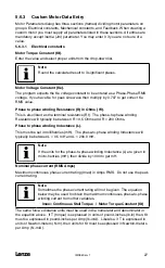
5.5.3 Setting Up motor
MotionView Motor Group on the left tree shows the currently selected motor. You can
click “CLICK HERE TO CHANGE” to view selected motor parameters or select new
motor.
MotionView’s <Motor Group> folder and its contents
Summary of Contents for SimpleServo 94
Page 1: ...MODEL 94 USERS MANUAL IMS94S mv1 ...
Page 12: ...l IMS94S mv1 10 3 2 Clearance for Cooling Air Circulation ...
Page 56: ...l IMS94S mv1 54 ...
Page 57: ...IMS94S mv1 l 55 ...
Page 58: ...l IMS94S mv1 56 ...
Page 59: ...IMS94S mv1 l 57 ...
Page 60: ...l IMS94S mv1 58 ...
Page 61: ...IMS94S mv1 l 59 ...
Page 62: ...l IMS94S mv1 60 ...
Page 63: ...IMS94S mv1 l 61 ...
Page 64: ...l IMS94S mv1 62 ...
Page 65: ...IMS94S mv1 l 63 ...


