IMS94S-mv1
l
41
7.2 Diagnostic LED’s
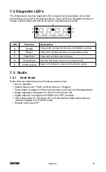
The SimpleServo has five diagnostic LEDs mounted on the periphery of the front
panel display as shown in the drawing below. These LEDs are designed to help you
monitor system status and activity as well as troubleshoot any faults.
LED
Function
Description
A
Enable
Orange LED indicates that the drive is ENABLED (running).
B
Regen
Yellow LED indicates the drive is in regeneration mode.
C
Data Entry
Yellow LED will flash when changing.
D
Comm Fault
Red LED illuminates upon a communication fault.
E
Comm Activity
Green LED flashes to indicate communication activity.
7.3 Faults
7.3.1 Fault Event
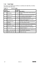
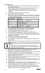
When drive encountered any fault following events occur:
• Drive is disabled
• Internal status set to “Fault” and Run Status to “Stopped”
• Fault number is logged in drives internal memory and can be interrogated later
• Digital output(s) if configured for “Run Time Fault” turn ON
• Digital outputs (if configured for READY) turn OFF (inactive)
• LED display shows F_XX where XX is current fault two-letter abbreviation or
number if display is in STATUS mode.
• “Enable” LED turns OFF
Summary of Contents for SimpleServo 94
Page 1: ...MODEL 94 USERS MANUAL IMS94S mv1 ...
Page 12: ...l IMS94S mv1 10 3 2 Clearance for Cooling Air Circulation ...
Page 56: ...l IMS94S mv1 54 ...
Page 57: ...IMS94S mv1 l 55 ...
Page 58: ...l IMS94S mv1 56 ...
Page 59: ...IMS94S mv1 l 57 ...
Page 60: ...l IMS94S mv1 58 ...
Page 61: ...IMS94S mv1 l 59 ...
Page 62: ...l IMS94S mv1 60 ...
Page 63: ...IMS94S mv1 l 61 ...
Page 64: ...l IMS94S mv1 62 ...
Page 65: ...IMS94S mv1 l 63 ...

