background image

- 5 -

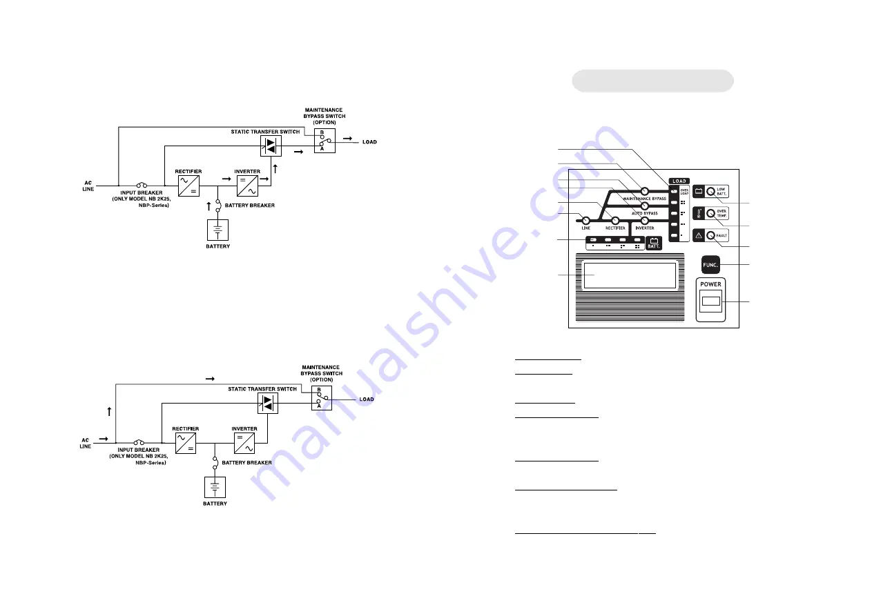
2.2.3 When utility power fail but loads are normal

Above diagram shows how UPS works when utility power fails such as

blackout, brownout, under voltage, over voltage or frequency fault and UPS

has less than 100% load.  UPS draws backup power from battery to invert to AC

power and continuously supplies to load.

2.2.4 Use maintenance bypass switch when UPS is malfunction (option)

Above diagram shows how system works when UPS is malfunction.

User is allow to temporary run the system by turning the manual bypass switch

from position A to B.  All loads will get power supplied directly from utility line.

Then, contact us or our nearest service center.

- 6 -

FRONT AND REAR PANEL

3.1.1

3.1.2

3.1.12

3.1.11

3.1.10

3.1.7

3.1.8

3.1.6
3.1.5

3.1.4

3.1.3

3.1.9

3.1.13

3.1 Front panel

3.1.1 POWER  button: The button to turn on and turn off the UPS.

3.1.2 FUNC. button: The button to mute alarm sound or turn on the LCD's back light;

The back light will turn off automatically in 10 seconds after release this button.

3.1.3 LINE indicator: The Indicates when utility line normally.

3.1.4 RECTIFIER indicator: The indicator is displayed when utility line normally,It

                       supplies power to the UPS in rectifier section and supplies power to charge

                       battery and loads normally.

3.1.5 INVERTER  indicator:  The indicator is display when the load is consuming high

quality power from inverter section.

3.1.6 AUTO BYPASS indicator: The indicator is displayed when load is consuming

power from utility line. It is possible that you connected more than 100% load

to UPS or INVERTER section is malfunction.

3.1.7 MAINTENANCE BYPASS indicator: The indicator is displayed when

MAINTENANCE BYPASS SWITCH is at position B or maintenance bypass circuit

breaker is at position ON (for NBP-0811-1011 only). At this moment, power

that  supplies  to load is from utility line.

Summary of Contents for NB 1K25

Page 1: ...NBP series NB series TRUE ON LINE DOUBLE CONVERSION UPS LEN MAN UPS 068 Rev 3 00 2008 www leonics com e mail global_business leonics com U S E R S G U I D E ...

Page 2: ...CONTENT SAFETY INSTRUCTIONS 1 INTRODUCTION 3 FRONT AND REAR PANEL 6 INSTALLATION 14 OPERATION 16 TROUBLESHOOTING 19 MAINTENANCE 20 ...

Page 3: ... plugging and unplugging the load in order to avoid electric shock from touching two surfaces with different potential 1 1 8 It is recommended to connect the UPS to a three wire AC source two poles plus ground which connects to a protected circuit such as employs a fuse or automatic circuit breaker 1 2 CAUTION Safety guide for installation and operation 1 2 1 Install the UPS in dry location with g...

Page 4: ... to avoid electric shock 1 3 5 Replace batteries with the same type and rating and follow the proper battery replacement procedure Vocabulary Load Any equipment which is plugged into the UPS and gets power from the UPS such as a computer printer fax machine or modem UPS NB Series and NBP series UPS VA The unit of UPS power rating showing its capacity 2 2 1 When utility power and loads are normal A...

Page 5: ...on and turn off the UPS 3 1 2 FUNC button The button to mute alarm sound or turn on the LCD s back light The back light will turn off automatically in 10 seconds after release this button 3 1 3 LINE indicator The Indicates when utility line normally 3 1 4 RECTIFIER indicator The indicator is displayed when utility line normally It supplies power to the UPS in rectifier section and supplies power t...

Page 6: ...al port to connect the LAN cable to computer network to monitor electrical and UPS status via SNMP HTTP Read more details in Net Agent manual 3 2 14 BATTERY TERMINAL for NBP0811 and NBP1011 The teminal for connecting to extension battery unit 3 1 13 LCD DISPLAY The screen to displays Input voltage Vin Output voltage Vout Battery Level B and Load level LD as shown in the picture below Note The valu...

Page 7: ...reaker OPTION Thecomponenttoswitchthepower source of loads to utility power when maintenance 3 1 18 SNMP AGENT OPTION The additional port to connect the LAN cable to computer network to monitor electrical and UPS status via SNMP HTTP Read more details in Net Agent manual 3 1 19 NO LOAD SHUT DOWN SWITCH The switch to enable automatic shutdown when there is no load and power fails No load means the ...

Page 8: ... 11 3 2 6 3 2 1 3 2 12 3 2 9 3 2 8 3 2 7 3 2 13 3 2 10 3 2 11 12 ...

Page 9: ...loads 3 2 11 GROUND The terminal for connecting to ground system 3 2 12 MAINTENANCE BYPASS SWITCH option Turn this switch to position B when UPS is under maintenance 14 INSTALLATION Model Input cable mm2 Output cable mm2 Earth cable mm2 Battery cable mm2 NB2K25 2 5 4 1 5 2 5 2 5 4 NBP 3K25 4 2 5 2 5 4 NBP 5K25 6 4 4 NBP 6K25 6 6 6 NBP 0811 10 6 10 6 6 NBP 1011 16 16 10 6 10 4 1 Connect the RS 232 ...

Page 10: ...rn on INPUT circuit breaker 5 1 2 2 Turn on POWER button and wait until INVERTER indicator is lit 5 1 2 3 Turn on BATTERY circuit breaker 5 1 3 Model NBP 0811 and NBP 1011 5 1 3 1 Turn on INPUT circuit breaker 5 1 3 2 Turn on POWER button and wait until INVERTER indicator is lit 5 1 3 3 Turn on BATTERY circuit breaker 5 1 3 4 Turn on OUTPUT circuit breaker Note When the UPS is out of order turn on...

Page 11: ...ch as when user turns on computers When the loads consume power less than 125 for 10 seconds UPS switches back to normal operation mode 5 3 4 If you connect loads to UPS more than 100 OVERLOAD indicator is lit we recommend you to unplug some of them until load is less than 100 to let loads get high quality power from UPS and backup power from battery Note LEONICS suggests that for highest reliabil...

Page 12: ... UPS is turned on UPS does not supply backup power when power fails No indicator displays at the panel when the UPS is turned on UPS does not supply backup power when power fails MODEL PROBLEM SOLUTION 20 6 2 How to turn on INPUT circuit breaker for NB2K25 NBP 3K25 NBP 5K25 NBP 6K25 NBP 0811 and NBP 1011 6 2 1 Turn off the UPS by pressing the POWER button at the front panel 6 2 2 Turn on the INPUT...

Page 13: ...n user wants to use the UPS plug the INPUT CABLE to wall outlet utility line Turn on POWER button and wait until the ventilation fan blows Then turn on BATTERY circuit breaker 7 4 2 Model NB 2K25 NBP 3K25 NBP 5K25 and NBP 6K25 7 4 2 1 Turn off the UPS by pressing the POWER button at the front panel 7 4 2 2 Turn off the BATTERY circuit breaker 7 4 2 3 Turn off the INPUT circuit breaker 7 4 2 4 When...

Reviews: