background image

- 12 -

 backup mode).

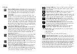
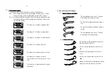
3.1.4 Overload Alarm (Lamp no. 3: red):  Shows load status. It will be lit when your

connecting loads are exceeding the UPS capacity.

3.1.5 Load Level:  Shows how much power your loads are consuming compared

to the UPS capacity from low to high level.

3.1.5.1 For the UPS with LED display (Lamp no.  4-7:green): Each lamp

represents 25% of full load capacity and starts from Lamp no. 4 to 7.

Please refer to section 6.2 The meaning of LED display.

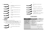
3.1.5.2 For the UPS with LCD display:  Each bar represents 25% of full load

capacity and starts from the thin bar to the thick bar.  Please refer to

section 6.3 The meaning of LCD display.

3.1.6 Input Voltage: Shows the normal mode or stabilizer mode status.

3.1.6.1 For the UPS with LED display (Lamp no. 8-11: green): One of 4 lamps

lights or blinks only at a time.  Please refer to section 6.2 The meaning

of LED display.

3.1.6.2 For the UPS with LCD display: One of 4 symbols lights or blinks only at

a time.  Please refer to section 6.3 The meaning of LCD display.

3.1.7 Battery Level: Shows the battery voltage from low to high level.

3.1.7.1 For the UPS with LED display (Lamp no.  4-11:  green): Shows battery

voltage presents by lamp no. 4 to 11 from low to high level.  In normal

mode, these lamps show load level and input voltage.  The display

changes to battery level display only when switch display mode or

the UPS is supplying backup power from battery.  To switch to battery

level display, please refer to section 5.5 Switch display from input

voltage - load level to battery voltage level or vice versa.

(Please refer to section 6.2 The meaning of LED display.)

3.1.7.2 For the UPS with LCD display:  Each bar represents backup power in

the battery which from the thin bar to the thick bar.  Thin bar stands

for low battery and 5 following bars represent 20% of full power each.

(Please refer to section 6.3 The meaning of LCD display.)

3.1.8 Replace battery: Indicates replace battery status (for UPS with LCD display).

Replace the battery when this messages and Low Battery/Replace Battery lamp

lights.

- 13 -

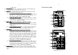
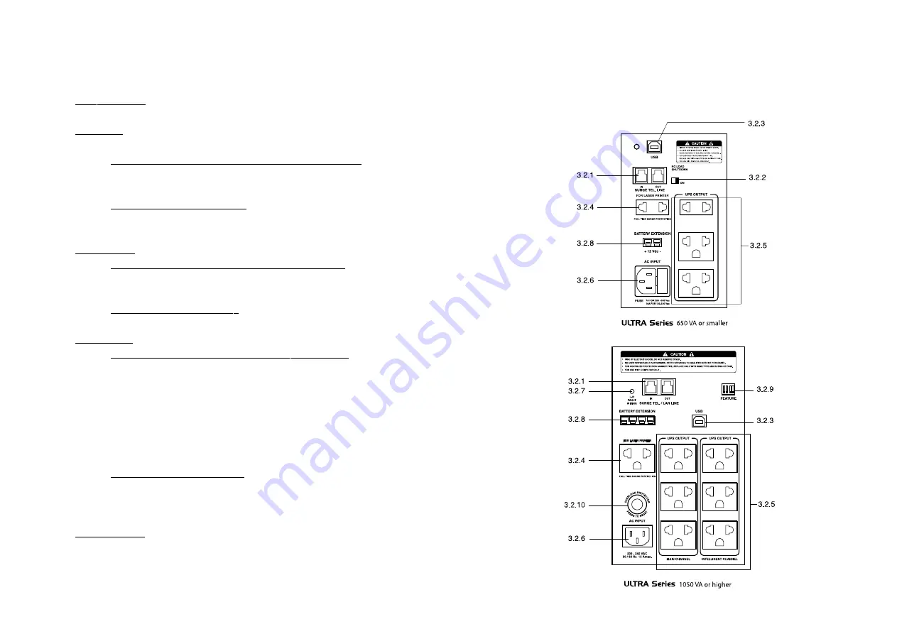
3.2 Rear panel description

Summary of Contents for Ulta Series

Page 1: ......

Page 2: ...nd quick reference for our service please fill the requested information in the blanks below UPS Model __________________________________ Serial Number __________________________________ Purchased dat...

Page 3: ...including UPS to prevent it from lightning 1 2 11Use soft cloth to clean the UPS when it is turned OFF DO NOT clean it with solvent 1 2 12DO NOT use the UPS with life recovery instruments The failure...

Page 4: ...ced Load Outlet Management ALOM which the user can program to turn off a low priority outlet when there is a low battery or overload condition for 1050VA or higher only For the UPS with LED display an...

Page 5: ...e Power Watcher provides information about load conditions whether or not you are overloading your ULTRA Series UPS PowerWatcher is continuously monitoring in real time both for the stabilizer and inv...

Page 6: ...et the intelligent output channel to cut off power to low priority loads when the UPS is overloaded over temperature or has a low battery available on 1050 VA or higher model only 8 Hot Swappable Batt...

Page 7: ...y power status Lit UPS is operating under its normal mode Blink UPS is operating in the backup mode Note 1 For the UPS with inverter temperature sensor option It will be blink fastly when the temperat...

Page 8: ...inks only at a time Please refer to section 6 3 The meaning of LCD display 3 1 7 Battery Level Shows the battery voltage from low to high level 3 1 7 1 For the UPS with LED display Lamp no 4 11 green...

Page 9: ...3 2 5 2 Intelligent Channel A supplemental outlets that the user can manage and control by Easy Mon X Software See item 12 2 The Intelligent Channel can be set to permanently turn on or can be set to...

Page 10: ...h enable disable ULTRA Series UPS 650VA or smaller ULTRA Series UPS 1050VA or higher Set the dip switch SW1 to ON as shown if you want the UPS to shutdown automatically in backup mode when the load is...

Page 11: ...wer cord to the electrical outlet Press the multi function switch for 0 5 second then release All indicator lights will blink after that UPS will start up the self test See details in section 5 3 1 Wh...

Page 12: ...de provided on the accompanying CD ROM 5 3 4 Auto test every 2 weeks If there is no manual or scheduled self test during the past 2 weeks the UPS will do a self test automatically You can also set the...

Page 13: ...e lit when load are between 51 to 75 Lamp no 4 5 6 and 7 are lit when loads are between 76 to100 Lamp no 4 5 and 6 are lit and lamp no 7 is blink when loads are over 100 and you should reduce the load...

Page 14: ...The lamp no 9 is lit when self test is cancelled because of battery power is too low The lamp no 11 is lit when it need to replace the battery 24 25 6 3 The meaning of LCD display 6 3 1 Input Voltage...

Page 15: ...en a stabilizer fault The second indicator is lit when a charger fault 27 The third indicator is lit when software failure The forth indicator is lit when CPU error The fifth indicator is lit when an...

Page 16: ...the load when it first starts Do nothing normal operation Turn off loads and wait until the AC source returns to normal Then turn on loads again or Usebackuppowerfrom UPS until battery low alarm alert...

Page 17: ...or 31 When the UPS warns you to replace the battery see details in item 6 2 3 2 and 6 3 4 2 Warning You can replace UPS s battery while it is operating But for your safety we recommends that you turn...

Page 18: ...reconnect each wires connection to each battery same as before Put the battery strip back in its position 9 6 Re screw the battery strip with the case 9 7 Replace and screw the front panel in place a...

Page 19: ...Driver to read the instructions for installing USB driver 12 5 Follow the instruction on screen to install UPS driver 12 6 When installation is completed restart computer 12 7 Install Easy Mon X Packa...

Reviews: