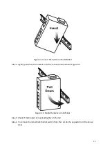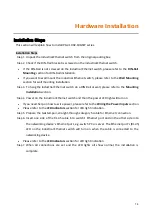
10
Wiring the Fault Alarm Contact
The fault alarm contact is in the middle of the terminal block connector as the picture shows
below in Figure 2.11. By inserting the wires, it will detect the fault status including power
failure or port link failure (managed industrial switch only) and form a normally open circuit.
An application example for the fault alarm contact is shown below in Figure 2.11.
Figure 2.11: Wiring the Fault Alarm Contact
Caution:
The wire gauge for the terminal block should range between 12 ~ 24 AWG.
If only using one power source, jumper Pin 1 to Pin 5 and Pin 2 to Pin 6 to eliminate
power fault alarm.
Attention:
Le calibre des fils du bornier doit être compris entre 12 et 24 AWG. Si vous
n'utilisez qu'une seule source d'alimentation, jumelez les broches 1 à 5 et les broches 2 à 6
pour éliminer l'alarme de panne de courant.

