background image

Step 2


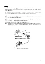
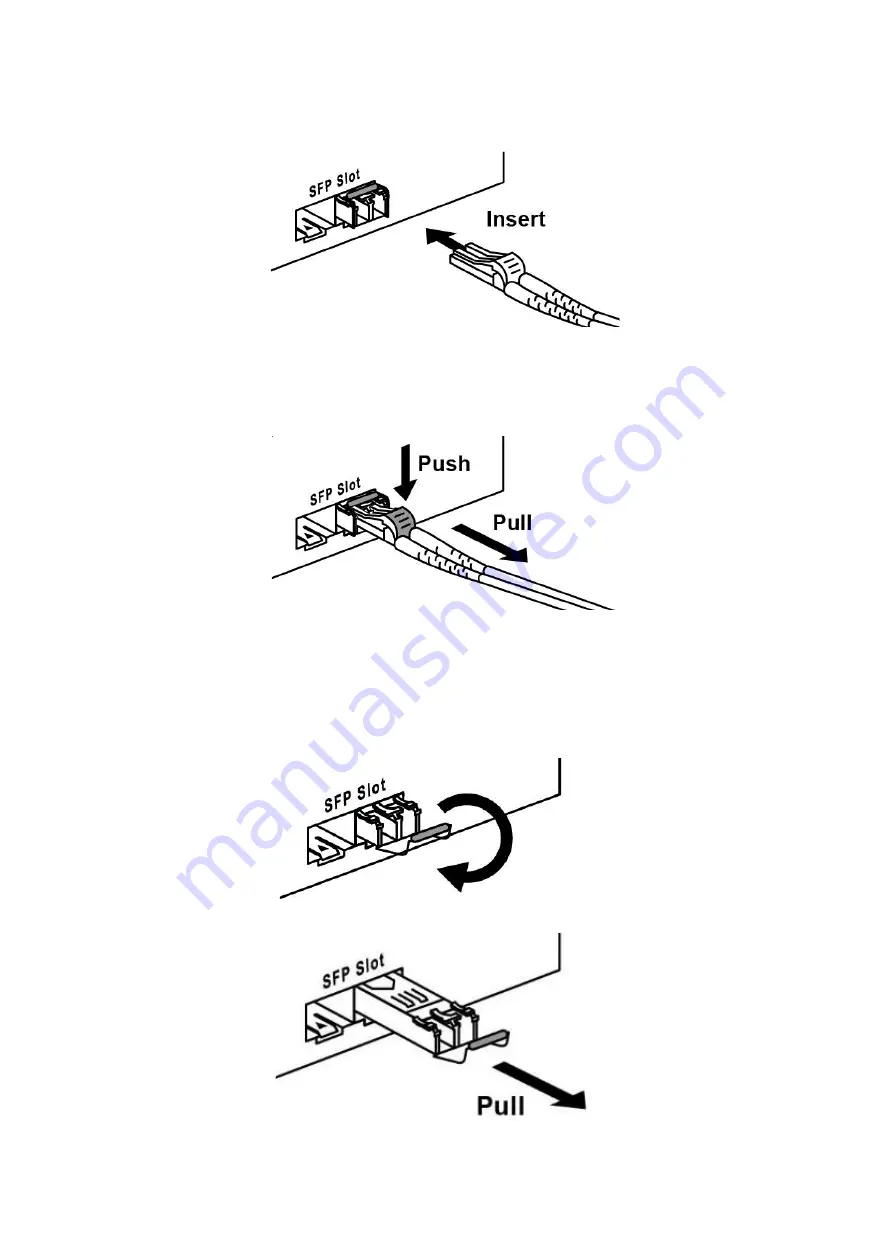
Insert the fiber cable of the LC connector into the transceiver as shown below in Figure 
2.6


Figure 2.6: LC Connector to the Transceiver 

 
To remove the LC connector from the transceiver, please follow the steps shown below: 

Step 1


Press the upper side of the LC connector from the transceiver and pull it out to release 
as shown below in Figure 2.7 


Figure 2.7: Remove LC Connector 


Step 2


Push  down  the  metal  clasp  and  pull  the  transceiver  out  by  the  plastic  part  as  shown 
below in Figure 2.8 


Figure 2.8: Pull Out from the SFP Slot 

Summary of Contents for PG5-2004-SFP Series

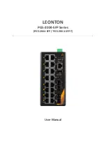
Page 1: ...LEONTON PG5 2004 SFP Series PG5 2004 SFP PG5 2004 SFP T User Manual ...

Page 2: ...ut not limited to the implied warranties of merchantability and fitness for a particular purpose Leonton Technologies Co Ltd may make improvements and or changes to the product and or specifications of the product described in this manual without prior notice Leonton Technologies Co Ltd will not be liable for any technical inaccuracies or typographical errors found in this guide Changes are period...

Page 3: ...ration FCC Cet équipement a été testé et reconnu conforme aux limites de la classe A pour les équipements numériques conformément à la section 15 des Réglementations FCC Ces limites sont conçues pour fournir une protection raisonnable contre toutes interférences nuisibles dans un milieu résidentiel Cet équipement génère utilise et peut émettre de l énergie de fréquence radio et s il n est pas inst...

Page 4: ...equired to take adequate measures CE Mark AVERTISSEMENT Ceci est un produit de classe A Dans un environnement domestique ce produit peut être utilisé en présence d interférences radio This document is the current official release manual Please check our website www leonton com for any updated manual or contact us by e mail sales leonton com ...

Page 5: ... 2 Hardware Description 3 Physical Dimensions 3 Front Panel 4 Top View 4 LED Indicators 5 Ethernet Ports 6 Cabling 7 Wiring the Power Inputs 9 Mounting Installation 10 DIN Rail Mounting 10 Wall Mounting 12 Hardware Installation 14 Installation Steps 14 Trouble Shooting 15 ...

Page 6: ...ned to meet any needs for industrial automation application and harsh environments Key Features Interface Performance All Copper ports support auto MDI MDI X function PG5 2004 SFP Embedded 16 10 100 1000Tx with 16 PoE PSE 30W Port 4 100 1000 Base F X SFP Slots Store and forward switching architecture 8K MAC Address Table Supports 9 6Kbytes Jumbo Frame 4Mbits memory buffer Power Input PG5 2004 SFP ...

Page 7: ...2 Pollution degree 2 ...

Page 8: ...rial use power The industrial Ethernet switch s hardware specs ports cabling information and wiring installation will be described within this user manual ATTETNION Si la tension CC est fournie par un circuit externe veuillez utiliser un dispositif de protection sur l entrée d alimentation Fourniture par courant industriel homologué UL Les spécifications matérielles les ports les informations de c...

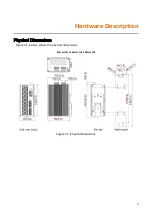
Page 9: ...3 Hardware Description Physical Dimensions Figure 2 1 below shows the physical dimensions 67mm W x 142mm H x 99mm D Figure 2 1 Physical Dimensions ...

Page 10: ...naged Ethernet switch is shown below in Figure 2 2 Figure 2 2 The Front Panel Top View Figure 2 3 below shows the top panel of the PG5 2004 SFP series switches that is equipped with two 4 pin removal terminal block connector for dual DC power inputs 48 55VDC Figure 2 3 Top Panel View ...

Page 11: ...ting 2 Configured event happens MASTER Green On ERPS Owner Mode Ring Master is ready Off ERPS Owner Mode is not active RING Green On ERPS Ring Network is active and works well Off ERPS Ring Network is not active GE LAN Port 1 16 Green On Connected to network 10 100 1000Mbps Flashing Networking is active Off Not connected to network PoE LAN Port 1 16 Green On Supplying power to the powered device O...

Page 12: ...traight Through Cable Pin Number Signal Pin Number Signal Pin Number Signal Pin Number Signal 1 RX 3 TX 1 RX 1 TX 2 RX 6 TX 2 RX 2 TX 3 TX 1 RX 3 TX 3 RX 6 TX 2 RX 6 TX 6 RX Table 2 2 1000BASE T RJ 45 Pin Assignments Table 2 3 Crossover Cable Straight Through Cable Pin Number Signal Pin Number Signal Pin Number Signal Pin Number Signal 1 TP0 3 TP1 1 TP0 1 TP1 2 TP0 6 TP1 2 TP0 2 TP1 3 TP1 1 TP0 3 ...

Page 13: ...e employ optional optical transceiver SFP that complies with IEC 60825 1 and classified as Class 1 laser product Attention Veuillez utiliser un émetteur récepteur optique SFP conforme à la norme CEI 60825 1 et classé comme produit laser de classe 1 To connect the transceiver and LC cable please follow below steps Step 1 Insert the SFP transceiver module into the SFP slot as shown below in Figure 2...

Page 14: ...ector from the transceiver please follow the steps shown below Step 1 Press the upper side of the LC connector from the transceiver and pull it out to release as shown below in Figure 2 7 Figure 2 7 Remove LC Connector Step 2 Push down the metal clasp and pull the transceiver out by the plastic part as shown below in Figure 2 8 Figure 2 8 Pull Out from the SFP Slot ...
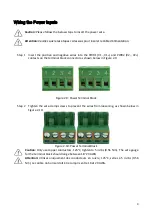
Page 15: ...nnector as shown below in Figure 2 9 Figure 2 9 Power Terminal Block Step 2 Tighten the wire clamp screws to prevent the wires from loosening as shown below in Figure 2 10 Figure 2 10 Power Terminal Block Caution Only use copper conductors 125 C tighten to 5 in lbs 0 56 Nm The wire gauge for the terminal block should range between 18 20 AWG Attention Utilisez uniquement des conducteurs en cuivre 1...

Page 16: ...gure 3 1 The Rear Side of the Switch and DIN Rail Bracket Follow the steps below to learn how to hang the industrial Ethernet switch Step 1 Use the screws to install the DIN Rail bracket on the rear side of the industrial Ethernet switch Step 2 To remove the DIN Rail bracket do the opposite from Step 1 Step 3 After the DIN Rail bracket is installed on the rear side of the switch insert the top of ...

Page 17: ...pull down the bracket on to the rail as shown below in Figure 3 3 Figure 3 3 Stable the Switch on DIN Rail Step 5 Check if the bracket is mounted tightly on the rail Step 6 To remove the industrial Ethernet switch from the rail do the opposite from the above steps ...

Page 18: ...Step 2 Place the wall mounting brackets on the top and bottom of the industrial Ethernet switch Step 3 Use the screws to screw the wall mounting bracket on the industrial Ethernet switch Step 4 Use the hook holes at the corners of the wall mounting bracket to hang the industrial Ethernet switch on the wall Step 5 To remove the wall mount bracket do the opposite from the steps above Figure 3 4 Remo...

Page 19: ...13 Below in Figure 3 5 are the dimensions of the wall mounting bracket Figure 3 5 Wall Mounting Bracket Dimensions ...

Page 20: ...to the Mounting Installation section Step 4 Power on the industrial Ethernet switch and then the power LED light will turn on If you need help on how to wire power please refer to the Wiring the Power Inputs section Please refer to the LED Indicators section for LED light indication Step 5 Prepare the twisted pair straight through category 5 cable for Ethernet connection Step 6 Insert one side of ...

Page 21: ...o assist in identifying problems the switch can be easily monitored with the LED indicators which help to identity if any problems exist Please refer to the LED Indicators section for LED light indication If the power indicator LED does not turn on when the power cord is plugged in the user may have a problem with the power cord Check for loose power connections power losses or surges at the power...

Reviews: