background image

This

 man

ual is

 to b

e giv

en to

the e

nd u

ser

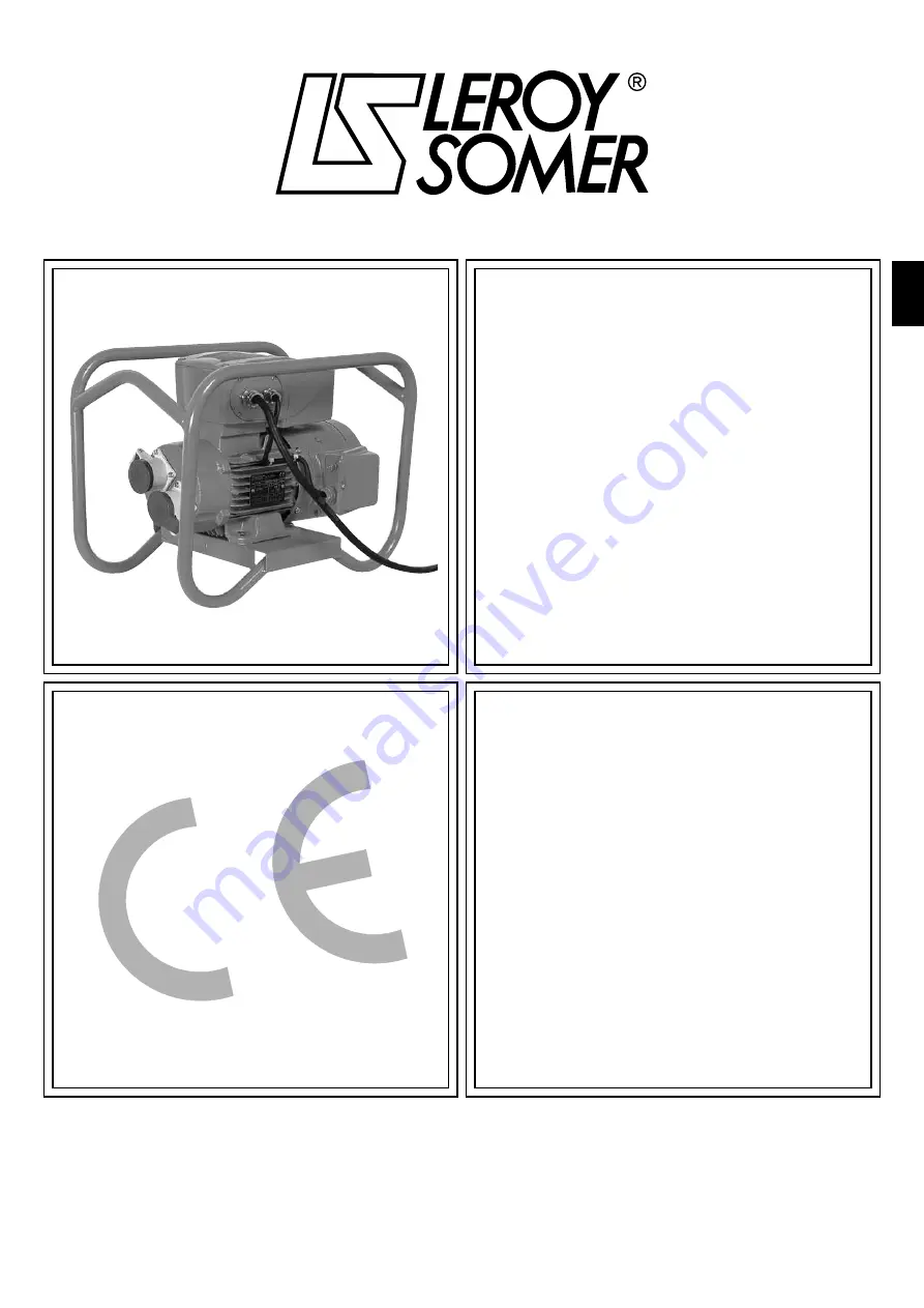
CONVERSTAT 

 Frequency changer 

Installation and maintenance 

3639 - 07.2007 / c

en

Summary of Contents for CONVERSTAT CVA 112 MG

Page 1: ...This manual is to be given to the end user CONVERSTAT Frequency changer Installation and maintenance 3639 07 2007 c en ...

Page 2: ...d to restarting which may be dangerous for certain machines or installations In such cases it is essential that the user takes appropriate precautions against the unit restarting after an unscheduled stop The variable speed drive is designed to be able to supply a motor and the driven machine above its rated speed If the motor or the machine are not mechanically designed to withstand such speeds t...

Page 3: ...and correct handling must be observed The climatic conditions specified in the technical manual must be observed 4 Installation The installation and cooling of equipment must comply with the specifications in the manual supplied with the product CONVERSTAT units must be protected against excessive stress In particular there must be no damage to parts and or modification of the clearance between co...

Page 4: ...4 INSTALLATION AND MAINTENANCE CONVERSTAT Frequency changer LEROY SOMER 3639 07 2007 c ...

Page 5: ...wer terminal blocks 10 3 3 1 Terminal block for power supply PB1 marked L1 L2 and L3 or L N 10 3 4 Terminal blocks for options 10 3 4 1 RS485 type serial link connector 10 3 4 2 P2 connector 10 4 COMMISSIONING 11 4 1 CONVERSTAT 11 4 1 1 Starting 11 4 1 2 Starting with the speed control button option BMA option 11 5 FAULTS DIAGNOSTICS 11 6 MAINTENANCE 12 6 1 Servicing 12 6 1 1 Drain holes 12 6 2 Me...

Page 6: ...en the generator set and the CONVERSTAT the subtransient reactance X d must be less than or equal to 7 In practice the generator set is dimensioned to have 2 5 times the power of the chargers CONVERSTAT 200 240 V single phase power supply 200 240 V 3 phase power supply 400 480 V 3 phase power supply CVA rating 42 V 200 Hz output CVA rating 42 V 200 Hz output CVA rating 42 V 200 Hz output kVA A No ...

Page 7: ...uctions described in this manual are adhered to CHARACTERISTICS CONVERSTAT Overload 150 of In for 60 s 10 times per hour Efficiency 97 5 x transformer efficiency CONTROL CONVERSTAT Frequency reference Analogue reference 0 V or 4 mA minimum speed 10 V or 20 mA maximum speed 0 10 V with integrated potentiometer BMA 31 32 option 0 10 V with remote potentiometer option 0 10 V with external reference 4...

Page 8: ...of the CONVERSTAT Passing the cable through a ferrite ring at 100 mm maximum distance from the CONVERSTAT Note Several control cables can pass through a single ferrite 1 5 6 Control circuit immunity when overvoltage occurs Immunity to overvoltages of control circuits or long cables connected outside a building The various drive input and output circuits conform to standard EN61000 6 2 1 kV relatin...

Page 9: ...be dangerous The voltages on the cables or connections of the mains supply the motor the braking resistor or the filter may cause fatal electric shocks Contact must be avoided in all circumstances The changer must be supplied via a circuit breaking device so that it can be powered down safely The changer contains capacitors which remain charged at a fatal voltage even after the power supply has be...

Page 10: ... or or circuit circuit breaker circuit breaker A A mm2 A A mm2 A A mm2 0 8 A 31M 7 16 2 5 A 31TL 5 8 1 5 A 31T 3 6 1 5 1 8 A 32M 14 25 2 5 A 32TL 7 16 2 5 A 32T 5 10 1 5 2 2 A 32TL 8 16 2 5 A 32T 6 10 2 5 4 7 A 32T 8 16 2 5 en 3 3 Power terminal blocks 3 3 1 Terminal block for power supply PB1 marked L1 L2 and L3 or L N This terminal block is used to connect the 3 phase power supply Screw terminal...

Page 11: ... knob 5 FAULTS DIAGNOSTICS Information relating to the status of the CONVERSTAT is provided by an indicator lamp inside the changer located on the local control BMA 31 32 option or by two indicator lamps Faults can be cleared by switching off the CONVERSTAT Colour and state of indic lamp CONVERSTAT status Checks to be performed Steady green No fault Mains present Flashing green Current limiting Ch...

Page 12: ... is advisable to leave the drain holes permanently open operating in environments with high levels of condensation Opening the holes periodically should be part of the regular maintenance procedure WARNING Certain components which are sensitive to electrostatic discharge may be destroyed simply by touching them Do not leave any metal object in the connection area as this could cause a short circui...

Page 13: ...05TT001 22 1 8 2x32x3 flat washer VIS008PS003 23 1 M8x20 H screw VIS008HF704 71 1 Electronic control unit 78 1 1 Cable gland and reducer JO1012PC100 JO1016PR010 78 2 1 Cable gland JO1008PC100 84 1 Terminal block with M5 terminals HE52A_1 85 1 Terminal block fixing screw VIS005XS703 100 8 Socket fixing screw VIS004XS703 101 2 32 A straight sockets CNX032P1027 102 2 BR438 seal JO1052JN005 200 1 Forc...

Page 14: ...1 8 2x32x3 flat washer VIS008PS003 23 1 M8x20 H screw VIS008HF704 71 1 Electronic control unit 78 1 1 Cable gland and reducer JO1012PC100 JO1016PR010 78 2 1 Cable gland JO1008PC100 84 1 Terminal block with M5 terminals HE52A_1 85 1 Terminal block fixing screw VIS005XS703 100 16 Socket fixing screw VIS004XS703 101 4 32 A straight sockets CNX032P1027 102 4 BR438 seal JO1052JN005 200 1 Forced ventila...

Page 15: ... option BMA 31 32 In addition to frequency control a run button and a stop button make it possible to control the CONVERSTAT locally once it has been switched on as required For a run command to be taken into account the button must be held down for one second 2 indicator lamps Connected on the P2 connector VMA 31 32 Do not wire the shunt between terminals 8 11 1 2 and or 9 11 en ...

Page 16: ...over of the CONVERSTAT Connect the RJ45 plug in the connector on the drive can be connected while powered up If there are no terminal blocks a fault appears on power up User 1 fault 8 2 Presentation of the LCD KEYPAD Reversal of direction when control via console mode is selected LCD display Inactive Run command Change between read mode and parameter setting and storage mode Fault reset or Stop co...

Page 17: ...s that can be displayed 05 01 Inverter frequency 01 49 Selected reference indicator 04 01 Total inverter current 01 50 Selected preset reference indicator 05 04 Inverter speed 01 01 Frequency speed reference selected 04 02 Active inverter current 02 01 Post ramp reference 05 02 Inverter voltage 06 22 Timer 05 05 DC bus voltage 06 23 Timer 07 01 ADI1 input level 06 24 Energy meter 07 02 ADI2 input ...

Page 18: ...supply 6 ADIO3 Analogue or digital input or analogue output 3 Assignment in standard configuration BMA option LED control CONVER STAT Terminal Designation Function 7 DIO1 Digital input or output 1 Assignment in standard configuration External fault management 8 DI2 Digital input 2 Assignment in standard configuration Run forward 9 DI3 Digital input 3 Assignment in standard configuration Stop 10 DI...

Page 19: ...he faults indicated by the display unit are listed in the following table in alphabetical order Cause Solution Inverter overload I t Check that the inverter is not overloaded Drive overload I t IGBT overheating sensor Decrease the inverter load Overcurrent at CONVERSTAT output Overload on 24 V supply or digital output Check the total current consumption Phase loss Check the mains supply 3 phases p...

Page 20: ...LEROY SOMER 16015 ANGOULÊME CEDEX FRANCE RCS ANGOULÊME N B 671 820 223 Limited company with capital of 62 779 000 www leroy somer com ...

Reviews: