10 / 31
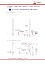
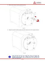
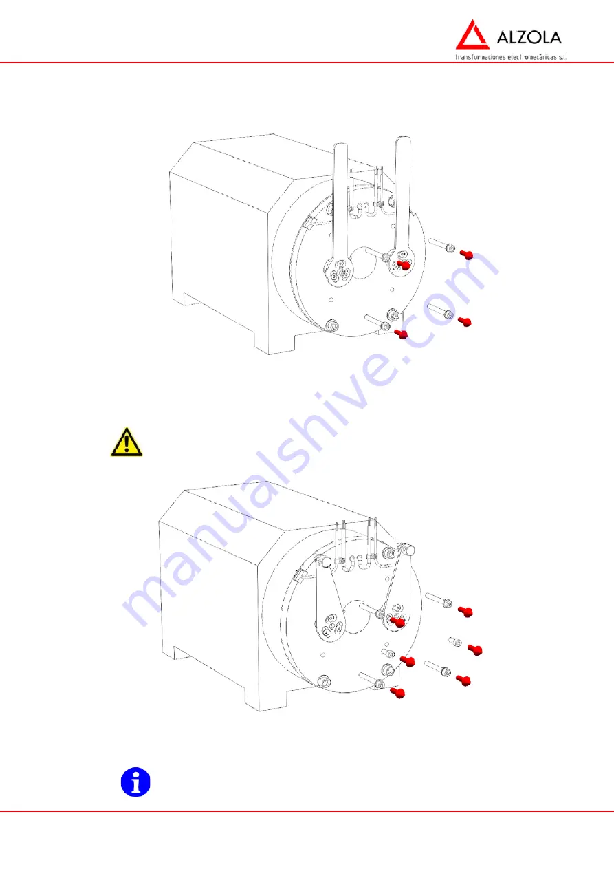
These screws are painted red. Clamp the mobile plates to the casing through the holes found in the
casing. They must be removed following the mechanical installation of the brake. Tightening them
will cause the mechanical release of the brake. They must never be placed in the installation, to avoid
them being accidentally tightened and causing the lift to fall.
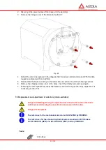
Fig. 6
After being removed, it is convenient to place the caps supplied with the brake to avoid the insertion
of particles in the inside of the brake.
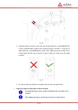
If the brake incorporates Bowden release levers (by cable), once the opening
cables have been placed in position, the red fixing screws must be removed
from the handles. If the screws remain tight they could cause the brake to be
released and the lift to fall.
Fig. 7
3.6 Positioning the rubber dust cover:
Position the rubber dust cover
before plugging in the electric
connection.
Summary of Contents for E27 Series
Page 4: ...4 E27 Gearless Installation and maintenance 5323 en 2018 04 c...
Page 15: ......
Page 46: ...30 31 NOTES...
Page 109: ......
Page 110: ......
Page 111: ......

