Construction, assembly and connection to power supply
Leuze electronic
RS4/AS-i
13
T
N
T
35/
7-
24V
DEUTSCH
ENGLISH
FRANÇAIS
IT
ALIANO
ESPAÑO
L
NEDERLANDS
4
Construction, assembly and connection to power supply
(AS-i)
4.1
Construction
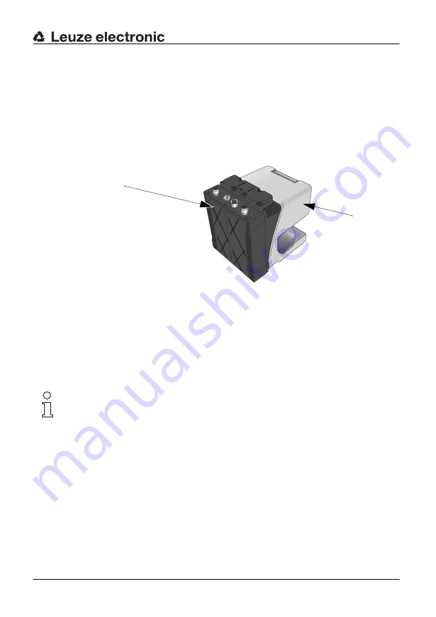
The RS4/AS-i consists of the RS4 laser scanner and the RS4/AS-i adapter. These have
already been connected to one another at the factory. The RS4/AS-i adapter manages the
processing of the standard RS4 data on the AS-Interface bus system.
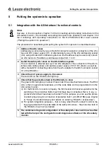
The safety-relevant OSSD signals and the diagnosis data of the RS4 are transmitted by
way of plug X1 (PIN1, PIN3) via AS-Interface to the AS-i safety monitor and AS-i Master.
In view of the high quantity of power it consumes, the RS4/AS-i requires a separate 24
VDC auxiliary power source, which is connected through plug X1 (PIN2, PIN4).
Socket X3 is responsible for the external switching of the four protective field and warning
field pairs.
Note:
For the wiring of the X3 socket, please observe the notes on the switching of protective
fields and warning fields in chapter 6 of the ROTOSCAN RS4-4 Connecting and Operating
Instructions.
If only one protective field is required, an M12 AC-M12-15M bridge plug (bridging PIN 1
and PIN 5) can be used for the wiring of protective field and warning field 1. See in this
connection chapter 8.4, Notes on ordering, RS4/AS-i accessories.
Plug X4 of the RS4/AS-i is intended for the connection of a restart button. This button
serves, on the one hand, for the unblocking of the scanner-internal start/restart interlock, if
this has been enabled; the button is also responsible for the acknowledgement of error
messages. This becomes necessary if the scanner has suffered a malfunction.
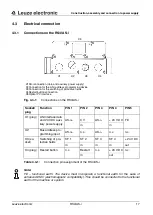
Fig. 4.1-1:
Construction of the RS4/AS-i
1 RS4/AS-i adapter
2 RS4 laser scanner
1
2


