Putting the system into operation
Leuze electronic
RS4/AS-i
19
T
N
T
35/
7-
24V
DEUTSCH
ENGLISH
FRANÇAIS
IT
ALIANO
ESPAÑO
L
NEDERLANDS
5
Putting the system into operation
5.1
Integration with the AS-Interface / functional controls
Note:
See also, in this connection, chapter 7 of the Connecting and Operating Instructions for the
AS-i safety monitor (“Functionality and putting the system into operation”) and chapter 10 of
the Connecting and Operating Instructions for the ROTOSCAN RS4-4 laser scanner
(“Putting the system into operation”).
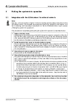
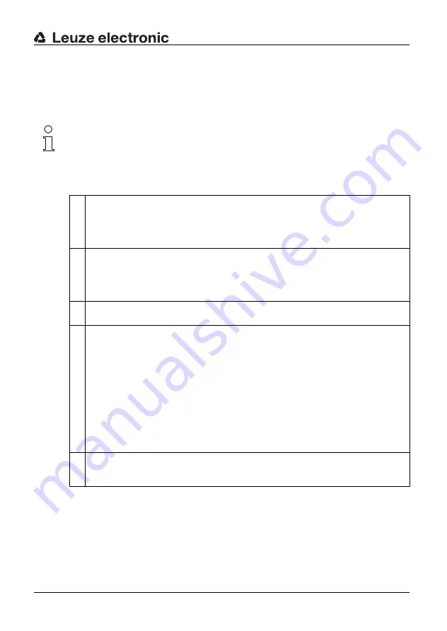
The procedure for assembling and putting the system into operation is described below:
1
Address the AS-i slave
Addressing is carried out by way of the M12 connector socket for connection of the AS-i
bus and 24 V power supply (X1), or alternatively by way of the AS-i addressing socket
(X4), using standard AS-i addressing devices. Each address may be used only once in
an AS-i network. Possible bus addresses range from 1 to 31.
2
Install the safety AS-i slave on the AS-Interface system
This connection is effected by way of an AS-i adapter for the connection of the AS-In-
terface data cable (yellow) and auxiliary power supply of 24 V DC (black), as well as
with a 5-pole M12 connecting cable from the AS-i adapter to the M12 connector socket
X1 of the RS4/AS-i.
3
Check the 24 V power supply to the sensor
The red LED on the RS4/AS-i will light up.
4
Check that the protective field of the RS4/AS-i is clear
The green LED will light up in about 20 seconds if the protective field is clear. The RS4/
AS-i is then in operational readiness, and the code table can be programmed into the
AS-i safety monitor.
L
For the RS4/AS-i to function properly, the M12 socket X3 that is responsible for the
switching of the protective fields must first have been connected, that is to say, a
protective field must have been activated. For this purpose you can use the protec-
tive field jumper plug for connection of protective field 1 (AC-M12-15M) (see chapter
8, “Scope of standard delivery and advice on ordering, RS4/AS-i accessories”).
L
For system integration purposes – that is to say, when the AS-i safety monitor is be-
ing programmed with the code table of the safety AS-i slave – the protective field of
the RS4/AS-i must not be violated.
5
The commissioning and configuration of the safety AS-i slave will now be effec-
ted with the help of the configuration and diagnosis software of the AS-i safety
monitor.


