Putting the system into operation
20
RS4/AS-i
Leuze electronic
DEUTSCH
E
NGLISH
FRANÇAIS
IT
A
LIANO
ESPAÑOL
N
EDERLANDS
5.2
Advice on malfunctioning and rectification of errors
Note:
See, in this connection, chapter 16 of the RS4’s Connecting and Operating Instructions
(“Error codes and their causes”), as well as chapter 9 of the Connecting and Operating
Instructions for the AS-i safety monitor (“Status messages, malfunctions and rectification of
errors”).
5.3
Extended possibilities of diagnosis by means of AS-Interface
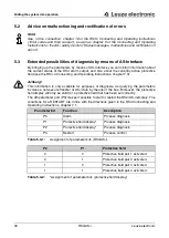
By bringing up the parameters by means of AS-Interface you can obtain information about
the current status of the RS4 alarm output, and also about the currently active protective
field (see the RS4-4 Connecting and Operating Instructions, chapter 7.3).
Achtung!
This information is only available for purposes of diagnosis, as querying the parameters
involves a non-secure transfer of AS-i data by means of the bus. Moreover, the protective
field display will only be valid for a protective field that has been set correctly.
The 4th parameter port (P3) makes it possible to start or restart the RS4/AS-i remotely. The
conditions for a RESTART are in line with the directions given in the RS4 Connecting and
Operating Instructions, chapter 7.1.
Parameter bit
Function
Description
P0
Alarm
Process diagnosis
P1
Protective field display*
Process diagnosis
P2
Protective field display*
Process diagnosis
P3
Restart
Process control
Table 5.3-1:
Assignment of parameter bits (RS4/AS-i)
P2
P1
Protective field
0
0
Protective field pair 1 activated
0
1
Protective field pair 2 activated
1
0
Protective field pair 3 activated
1
1
Protective field pair 4 activated
Table 5.3-2:
*Assignment of parameter bits (protective field display)


