Leuze
electronic
Operation
Leuze electronic
Technical Description BCL 90
105
T
N
T 35/
7-
24V
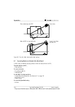
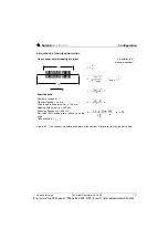
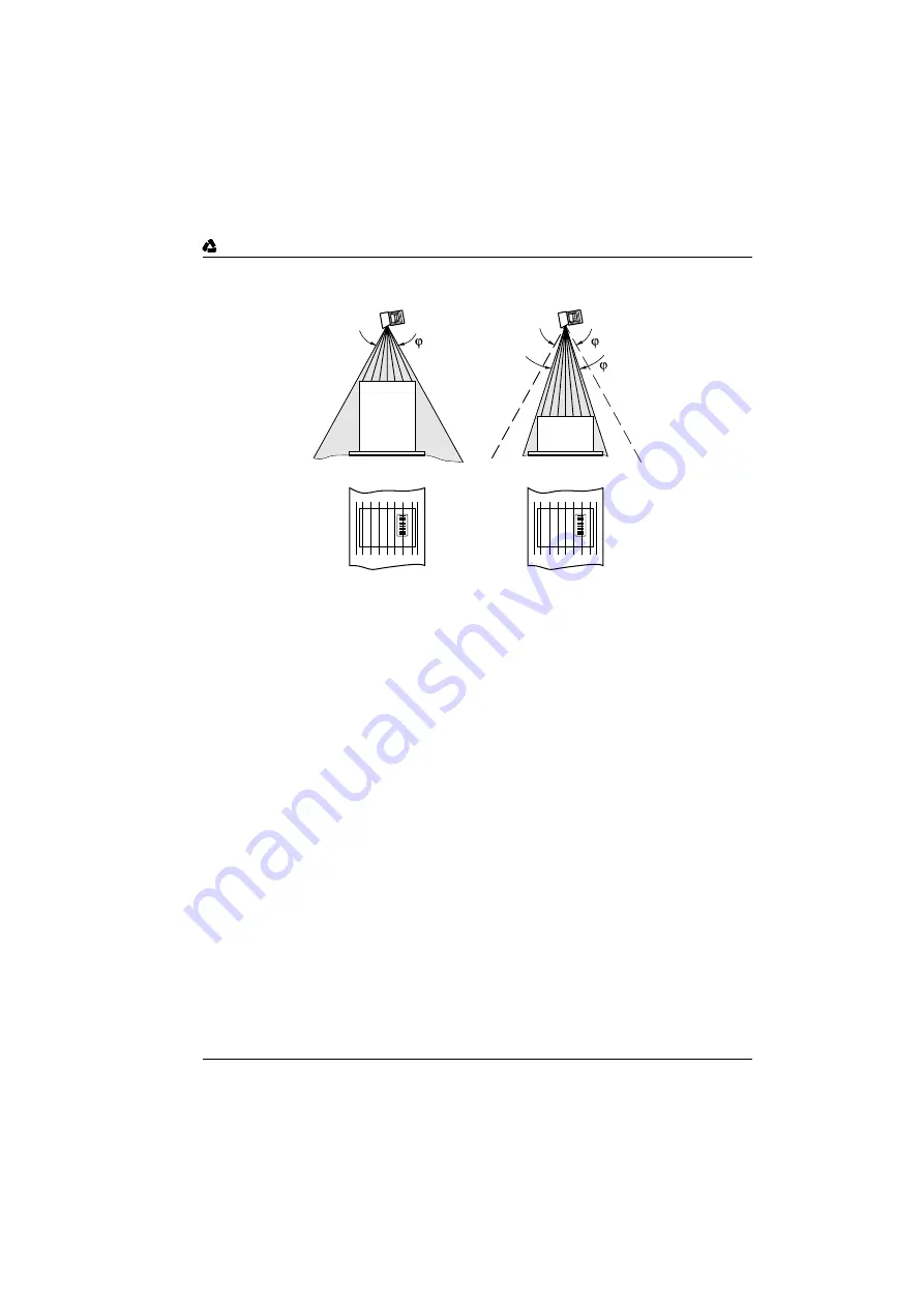
Figure 8.4: Oscillating mirror operating mode "oscillating at variable amplitude"
3. Operating mode "predefined position"
The BCL parks the oscillating mirror at the desired position. In this position, 10 CW corresponds to -
20°, 90 CW, on the other hand, +20° (See figure 6.8 on page 74). The predefined position in the base
setting is 50 CW (corresponds to 0°). The oscillation operation is switched off.
4. Operating mode "one-shot"
In one-shot, the oscillating mirror performs only one single specific oscillation for each scan gate time.
The movement consists of a forward and a return phase. For the oscillation, the starting position of
the scan line, the deflection speed and the valid distance configuration can be parameterized sepa-
rately for each phase. The end position of one of the phases always forms the starting position of the
other phase. Figure 8.5 shows an example for the application in object tracking. The front side of the
object moving towards the oscillating mirror is scanned once from top to bottom by the scan line during
the forward phase at a speed corresponding to that of the transport. A multiple switching of the focus
position is omitted as the required DOF is much smaller than that of a line scanner. In Section 9.1.2,
on page 113, the calculation of the starting position and of the deflection speeds at given transport
speed is described.
The following can be triggers for the one-shot:
• switched input "SE 5" or "SE 6"
• a command string (via the serial interface)
• the start of the scan gate time by the BCL
0
0
1
Oscillation frequency
constant
Same scan line density, regardless of object height
Limiting
the deflection width
(CW value)
Buy: www.ValinOnline.com | Phone 844-385-3099 | Email: CustomerService@valin.com


