Electrical connection
Leuze electronic
BPS 8
56
TNT
35/7-2
4
V
7.4
Electrical connection via connection unit MA 8-01 / MA 8-02
7.4.1
PWR IN HOST/RS485 connector – voltage supply/RS 485
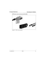
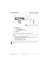
Figure 7.7: MA 8-01/MA 8-02 – Pin assignment PWR IN HOST/RS485 connector
Electrical data
Service interface
No MA 8-01/MA 8-02 connected
:
RS 232 with default data format,
9.6kBit/s, 8 data bits, no parity, 1 stop bit
With MA 8-01/MA 8-02 connected
:
RS 485 replaces RS 232
Switching input/output 1 switching input, 1 switching output, each is programmable
Switching input:
10 … 30VDC
Switching output:
I
max
= 60mA
output voltage = operating voltage
Operating voltage
10 … 30VDC
Power consumption
Max. 0.5W (without BPS 8)
PWR IN HOST/RS485 (5-pin connector, A-coded)
Pin
Name
Comment
1
VIN
Positive supply voltage: +10 … +30VDC
2
RS485B
RS 485 receive/transmit data
B-line
3
GND
Supply voltage: 0VDC
4
RS485A
RS 485 receive/transmit data
A-line
5
FE
Functional earth
Thread
FE
Functional earth (housing)
CAUTION
Degree of protection IP 67!
Degree of protection IP 67 is achieved only if the connectors and caps are screwed into
place!
3
2
1
4
5
RS485A
GND
VIN
FE
RS485B
PWR IN
HOST/RS485
M12 connector
(A-coded)


