Telegram
Leuze electronic
MA 258
i
53
TNT
35/7-2
4
V
10
Telegram
10.1
Structure of the fieldbus telegram
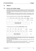
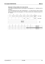
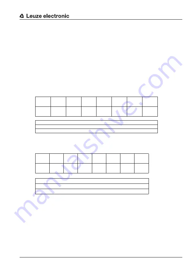
All operations are performed by control and status bits. Two bytes of control information
and two bytes of status information are available for this purpose. The control bits are a part
of the output module and the status bits are a part of the input bytes. The data starts with
the third byte.
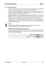
If the actual data length is longer than the data length configured in the gateway, only part
of the data is transmitted; the remaining data is lost. In this case, the DL (data loss) bit is set.
The following telegram structure is used between
PLC -> fieldbus gateway
:
This telegram structure is used between
fieldbus gateway -> PLC
:
Only the data part with the corresponding frame (e.g., STX, CR & LF) is then transmitted
between the fieldbus gateway and the Leuze end device. The two control bytes are
processed by the fieldbus gateway.
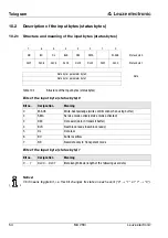
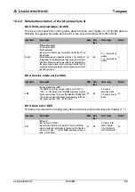
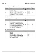
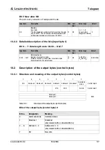
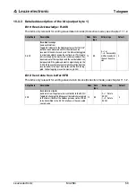
The corresponding control and status bits and their meaning are specified in section 10.2
and section 10.3.
Further information on the broadcast control bytes and address bits 0 … 4 can be found in
chapter "Modular interfacing unit MA 3x (S4 switch position C)" on page 110.
7
6
5
4
3
2
1
0
ND
Address 4
Address 3
Address 2
Address 1
Address 0
Broadcast
Command
mode
Control byte 0
CTB
SFB
R-ACK
Control byte 1
Data byte / parameter byte 0
Data
Data byte / parameter byte 1
…
7
6
5
4
3
2
1
0
ND
BO
DL
BLR
DEX
SMA
W-ACK
Status byte 0
DLC7
DLC6
DLC5
DLC4
DLC3
DLC2
DLC1
DLC0
Status byte 1
Data byte / parameter byte 0
Data
Data byte / parameter byte 1
…

