Commissioning and configuration
68
MA 258
i
Leuze electronic
12
Commissioning and configuration
12.1
Measures to be performed prior to the initial commissioning
Before commissioning, familiarize yourself with the operation and configuration of the
MA 258
i
.
Before connecting the supply voltage
,
recheck all connections and ensure that they
have been properly made.
The Leuze device must be connected to the internal RS 232 device interface.
Connecting the Leuze device
Open the housing of the MA 258
i
and lead the corresponding device cable (see chapter
14.6) through the middle threaded opening.
Connect the cable to the internal device interface (X30, X31 or X32,
see chapter 7.5.1
Use rotary switch S4 (see chapter 8.2.5) to select the connected device.
Now screw the PG cable gland into the threaded opening to provide strain relief and
ensure protection class IP 65.
Finally, close the housing of the MA 258
i
.
Attention!
Only then may the supply voltage be applied.
Upon startup of the MA 258
i
, the device selection switch is queried and the gateway auto-
matically sets itself to the Leuze device.
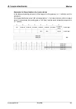
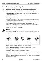
Figure 12.1: Connections of the MA 258
i
seen from below, device on mounting plate
Check the applied voltage. It must be in the range b18V … 30VDC.
Connecting functional earth FE
Ensure that the functional earth (FE) is connected correctly.
Unimpaired operation is only guaranteed when the functional earth is connected properly.
All electrical disturbances (EMC couplings) are discharged via the functional earth connec-
tion.
On delivery, the SWIO 1/2 are connected in parallel on PWR IN/OUT. This connection can
be separated with a jumper.
PWR OUT
VOUT 1
2
3
4
SWIO_2
SWIO_1
GND
FE
5
PWR IN
SWIO_1
SWIO_2
3
2
1
4
5
GND
VIN
FE
HOST / BUS IN
TD+ 1
2
3
4
RD+
RD-
TD-
LEUZE Device
BUS OUT
TD+ 1
2
3
4
RD+
RD-
TD-
M12 connector
(A-coded)
M12 socket
(A-coded)
M12 socket
(D-coded)
M12 socket
(D-coded)

