Functions
Leuze electronic
MSI-SR4B
10
4
Functions
Single-channel E-Stop circuit, manual start
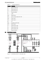
see figure 7.3
After applying the supply voltage to A1 and A2 and with the E-Stop button not actuated, relays K1 and K2
pick up upon actuation of the start button and lock. The release circuits 13-14, 23-24 and 33-34 close,
signal circuit 41-42 opens. Upon actuation of the E-Stop button, K1 and K2 go dead and drop out. The
release circuits open, the signal circuit closes. With one-channel E-Stop wiring, up to category 2 acc. to
EN ISO 13849-1: 2009 is achieved. Earth faults in the button circuit are detected.
Two-channel E-Stop circuit, manual start
see figure 7.3
Function/operating principle as described above. In addition, contactor contacts K1 and K2 are looped into
the start circuit (reset) (EDM).
With two-channel E-Stop wiring, up to category 4 acc. to EN ISO 13849-1: 2009 is achieved.
Downstream safety circuit for optoelectronic protective devices type 4, EN 61496-1
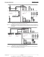
see figure 7.1, see figure 7.2
Optionally, light beam safety devices of type 4 can be connected with relay outputs (see figure 7.1) or with
fail-safe semiconductor outputs (see figure 7.2). When calculating the safety distance, the regression
delay of the MSI-SR4B of 10 ms must be included. As an alternative to the start circuit, a bridge can be
placed between S34 and S35 for automatic start. With this operating mode, it must not be possible to reach
or step behind the light beam safety device.
Two-channel sliding safety guard monitoring
see figure 7.3
Based on the specified signal sequence, when using two, forced position switches, the direction-depen
-
dent actuation of the contacts, e.g. of a safety guard, is monitored. For automatic start (bridge S34 - S35),
reaching or stepping behind must not be possible.
Signal sequence monitoring
The function expects the first signal at S22 and the second signal at S12. The time offset is arbitrary. If,
due to, e.g., misalignment of a contact actuator, the times of the signals are swapped, this is tolerated up
to max. 20 ms. Afterwards, the release circuits of the MSI-SR4B close. Signal sequence monitoring is only
active if wired for automatic start. The EDM signal must be applied for max. 20 ms at S12 after the signal
is received.
Monitoring of the S inputs
In the event of a cross connection at inputs S12 and S22 or of a short circuit of input S12 to ground, output
relays K1 and K2 are switched off via an electronic fuse. The MSI-SR4B is again ready for operation
approx. 2 s after the cause of the malfunction has been eliminated.
Start button monitoring during manual start
see figure 7.1
To detect static faults or blocking of the start button, the button function is monitored for signal changes.
Enabling occurs when the button is released (1/0 signal change). This function is deactivated during auto
-
matic start.
Contactor monitoring (EDM) with manual start
see figure 7.1
For function monitoring of the external contactors, their NC contacts (K4, K5) are looped into start circuit
S35 with start button in series.
Contactor monitoring (EDM) with automatic start
see figure 7.2
For function monitoring of the external contactors, their NC contacts (K4, K5) are looped in between S34
and S35 in series.
Phone: 800.894.0412 - Fax: 888.723.4773 - Web: www.clrwtr.com - Email: info@clrwtr.com

