Leuze electronic GmbH + Co. KG
Post-box 1111 D-73277 Owen-Teck Tel. +49 7021 5730
IT 3800g - 02
www.leuze.de
Leuze
electronic
Switching off the computer
Information on switching off and shutting down the connected computer - which must always be performed before connecting
peripheral devices, such as a scanner - can be found in the appropriate operating instructions for your computer.
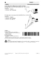
Connecting the IT 3800
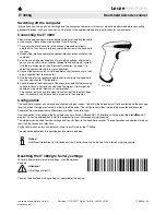
Shown in the adjacent figure are the individual steps for installing the cable
on the scanner; these steps are described in the following.
1.
To secure the interface cable to the scanner, proceed as follows:
plug the RJ 41 connector into the socket on the bottom of the hand-held
scanner.
2.
Connect the interface cable to the appropriate connection socket on the
computer.
3.
You may need a power supply unit for supplying voltage; alternatively,
you can use a cable which supplies voltage from the computer system.
Use the pin assignments (see "Electrical connection" on page 1) to
select the appropriate cable for your application.
4.
Connect the power supply unit to the power socket (not necessary if volt-
age is supplied from the computer).
5.
Use the code for the respective application to configure the hand-held
scanner, see chapter "Configuration".
6.
Check the operational readiness of the scanner by pointing the scanning
surface towards a flat surface and pulling the trigger. A red target line
should now be visible. Now scan a sample label.
The scanner emits an audible signal to confirm that the label has been
read; if necessary, the data are now passed on to the computer.
Configuration
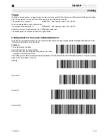
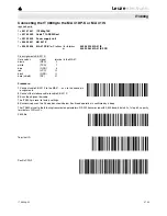
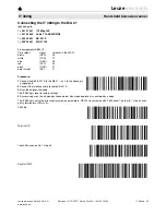
The hand-held scanner can always be configured using bar codes. To do this, the barcode must first be selected on the package
insert and then the trigger actuated in order to read the code. The configuration is then immediately accepted and executed.
Several of the most important configurations are listed in the following.
A second option is to configure the hand-held scanner with the USB and RS 232 interfaces with the aid of the
VisualMenu
PC
program. You can download and install this program from our homepage at
www.leuze.de.
The program can be used to make settings and transfer them to the hand-held scanner. The configuration can also be stored so
that it can be reused at a later time.
Further information on this can be found in the User's Guide for the IT 3800g.
The standard applications are described and summarised below.
Notice!
Additional information on the device and short instructions can be found on the Internet at www.leuze.de.
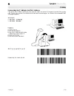
Resetting the IT 3800g to factory settings
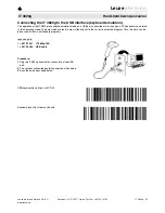
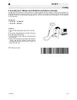
To reset all parameters to factory settings, scan the adjacent
barcode.
Attention!
All settings are lost!!!
You may then continue making settings or operation of the device.
Cable latch
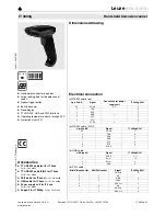
IT 3800g
Hand-held barcode scanner

