Device description
Leuze electronic GmbH + Co. KG
MLC 530 SPG
15
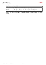
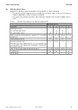
State
Description
LED1
LED2
Green
OFF
Normal operation on channel 1
Green
Green
Normal operation on channel 2
Green, flashing
OFF
Reduced operating range on channel 1
Green, flashing
Green, flashing
Reduced operating range on channel 2
Red
OFF
Device error
Green
Red, flashing
External test (MLC 502 only)
3.3.2
Operating indicators on the MLC 530 SPG receiver
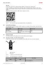
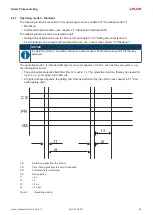
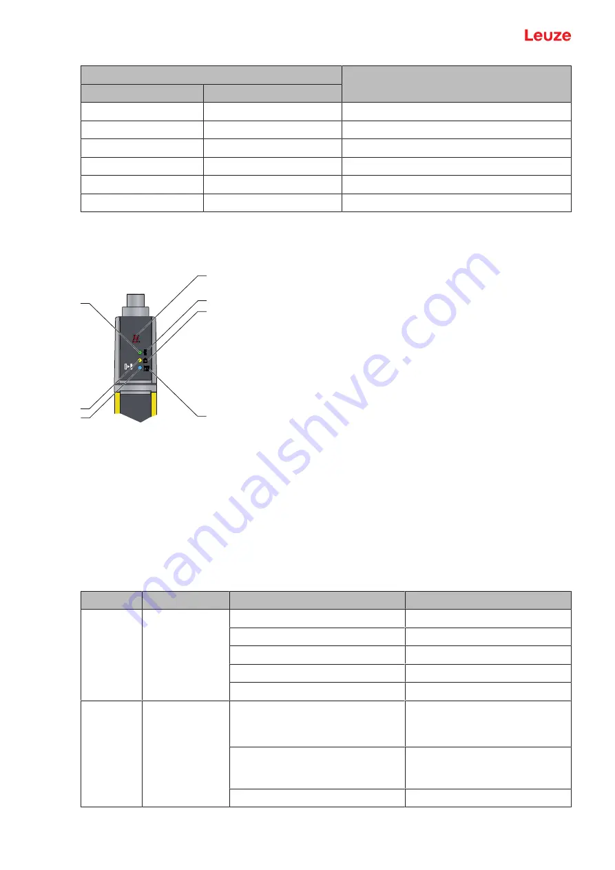
Three LEDs and a 7-segment display for visualizing the operating state are located on the receiver:
1
4
5
6
2
7
3
1
LED1, red/green
2
LED2, yellow
3
LED3, blue
4
OSSD icon
5
RES icon
6
Blanking/SPG icon
7
7‑segment display
Fig. 3.4:
Indicators on the MLC 530 SPG receiver
Tab. 3.3:
Meaning of the LEDs on the receiver
LED
Color
State
Description
1
Red/green
OFF
Device switched off
Red
OSSD off
Red, flashing slowly (approx. 1 Hz)
External error
Red, flashing fast (approx. 10 Hz)
Internal error
Green
OSSD on
2
Yellow
OFF
• RES activated and enabled
• or RES blocked and protective
field interrupted
ON, OSSD off
RES activated and blocked but
ready to be unlocked - protective
field free
ON, OSSD on
CS switching signal is applied


