Troubleshooting
Leuze electronic GmbH + Co. KG
MLC 530 SPG
85
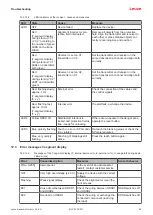
Tab. 12.2:
LED indicators at the receiver - causes and measures
LED
State
Cause
Measure
LED1
OFF
Device failed
Replace the device.
Red
(7-segment display
during start-up: “C1”
or “C2” according to
the number of green
LEDS on the trans-
mitter)
Alignment incorrect or pro-
tective field interrupted
Remove all objects from the protective
field. Align the transmitter and receiver to
each other or place blanked objects cor-
rectly concerning size and position.
Red
(7-segment display
during start-up: “C1”.
LEDs on transmitter:
both green)
Receiver is set on C1,
transmitter on C2
Set the transmitter and receiver on the
same transmission channel and align both
correctly.
Red
(7-segment display
during start-up: “C2”.
LED1 on transmitter:
green)
Receiver is set on C2,
transmitter on C1
Set the transmitter and receiver on the
same transmission channel and align both
correctly.
Red, flashing slowly,
approx. 1 Hz
(7-segment display
“E x y”)
External error
Check the connection of the cables and
the control signals.
Red, flashing fast,
approx. 10 Hz
(7-segment display
“F x y”)
Internal error
If restart fails, exchange the device.
LED2
Yellow OSSD off
Start/restart interlock is
locked and protective field is
free - ready for unlocking
If there are no people in the danger zone,
operate the reset button.
LED3
Blue, quickly flashing Teach-in error or SPG condi-
tion violated
Re-teach the blanking areas or check the
SPG prerequisites.
Blue, very quickly
flashing
Teaching of blankings still
active
Press the teach button again.
12.3
Error messages 7-segment display
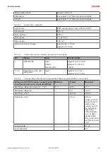
Tab. 12.3:
Messages of the 7-segment display (F: internal device error, E: external error, U: usage info during appli-
cation errors)
Error
Cause/description
Measures
Sensor behavior
F[No. 0-255]
Internal error
In the event of an unsuccessful
restart, contact customer service.
OFF
Very high overvoltage (± 40 V) Supply the device with the correct
voltage.
Flashing
Weak signal display
Check the alignment or clean the
front screens.
E01
Cross-circuit between OSSD1
and OSSD2
Check the wiring between OSSD1
and OSSD2.
OSSD switches off
E02
Overload on OSSD1
Check the wiring or exchange the
connected component (reducing
the load).
OSSD switches off


