background image


5

GENERAL INSTALLATION INSTRUCTIONS 


Foundations 


Fan foundation must be flat, level and rigid. Where foundation is not completely flat, shims must be 

placed under fan support at each anchor bolt as required. Bolting fan to an uneven foundation distorts 
alignment and causes vibration.  
Structural steel foundations should be heavily cross-braced for load support.  
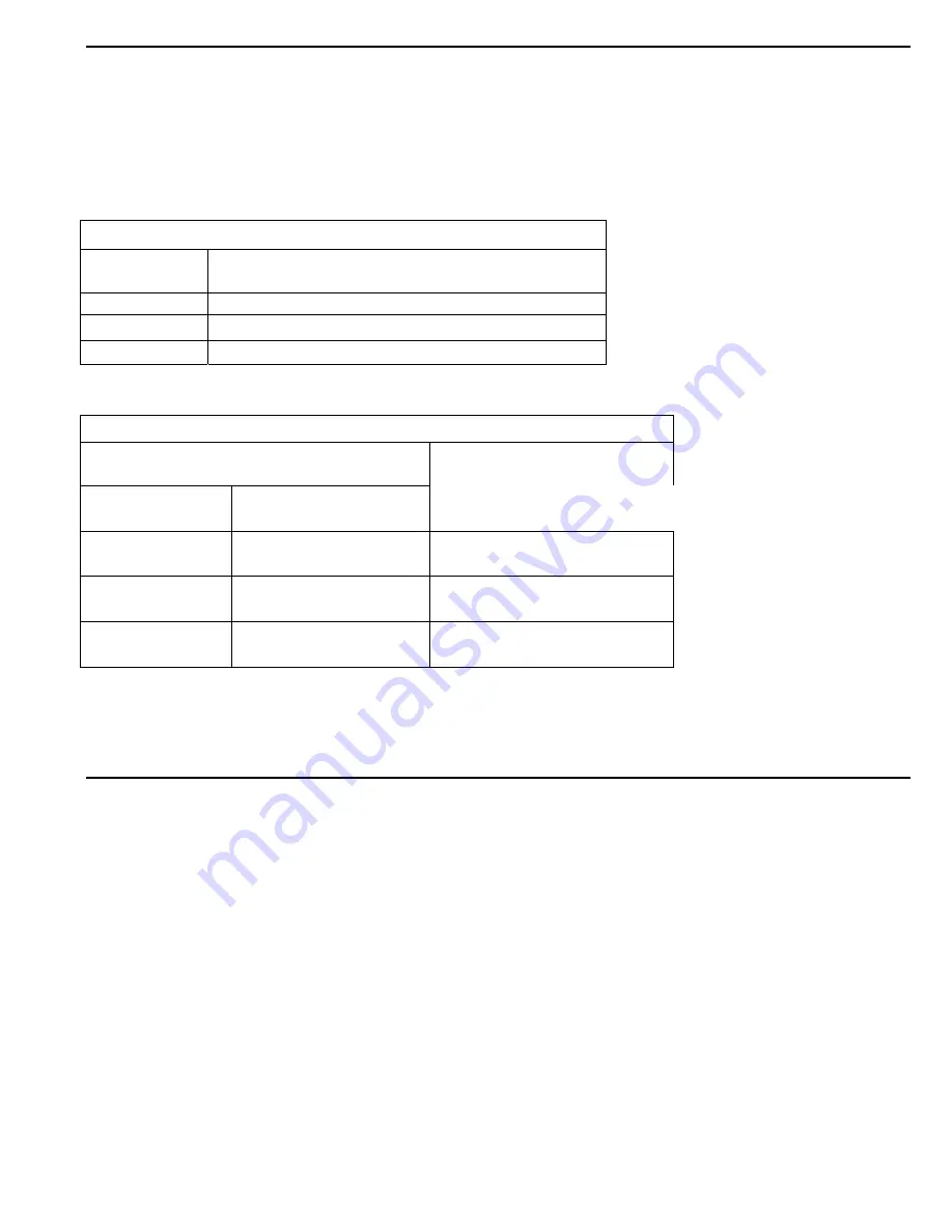
Table #1 


TORQUE VALUES FOR SPLIT TAPER BUSHINGS 


Bushing Size 


MINIMUM RECOMMENDED TORQUE 

(INCH-LBS)


H 95 

B & P 

192 

Q & R 

350 


Table #2 


SET SCREW TORQUE VALUES


SET SCREW SIZE


MINIMUM REQUIRED 

TORQUE (INCH-LBS)


Diameter & No. 

of Threads/Inch


Hex Size Across Flats 

(Allen Wrench)


1/4-20 

5/16-18 

1/8" 

5/32" 

65 

165 

3/8-16 

7/16-14 

3/16" 
7/32" 

228 
348 

1/2-13 
5/8-11 

1/4" 

5/16" 

504 

1104 


NOTE: 

If wheel set screws are loosened and/or wheel is removed from shaft, set screws 

must 

be replaced. 

Set screws cannot be used more than once. Use knurled, cup point set screws with a locking patch.  


OPERATION 


Before Connecting Power 


1.


Inspect all fasteners and retighten if necessary:  

a.


Foundation bolts.  

b.


Set screws in fan and wheel and V-belt drive (See Table #1 on preceding page).  

c.


Housing, bearing and motor mounting.  

2.


Inspection doors should be tight and sealed.  

3.


Bearings should be checked for alignment and lubrication (See Bearing Maintenance, pages 4 and 5).  

4.


Turn rotating assembly by hand to insure that it does not strike housing. If the wheel strikes the housing, 
the wheel may have moved on the shaft or the bearings may have shifted in transit. Correction 

must 

be 

made prior to start up.  

5.


Check motor to insure proper speed and electrical characteristics.  

6.


Check V-belt drive for alignment and correct belt tension.  

7.


After wiring, energize motor for one second to check for proper rotation.  


Summary of Contents for SQBI

Page 1: ...TALLER A FIRE PROTECTION EXPERT SHOULD BE OBTAINED IN THE EVENT THE PRODUCT IS INTENDED FOR USES WHICH PRESENT A POTENTIAL RISK OF FIRE OR FIRE PROPAGATION REFER TO APPROPRIATE AUTHORITIES AND DISCUSS YOUR INTENDED USE WITH A LEV CO REPRESENTANT WORKERS HANDLING EQUIPMENT OR SYSTEMS SHOULD BE INSTRUCTED TO CONDUCT THEMSELVES IN A SAFE MANNER The Local Exhaust Ventilation Company www LEV CO com sal...

Page 2: ...PARTS TO MAINTAIN WARRANTY TO ORDER SPARE PARTS CONTACT US 1050 BROCK ROAD Unit 22 24 Pickering ON CANADA L1W 3X4 Phone 905 831 7001 or 888 862 5356 Fax 905 831 7443 or 866 840 9923 E mail sales lev co com Website http www lev co com ...

Page 3: ...General Safety Notes 4 2 Receiving 4 3 Handling 4 4 General Installation Instructions 5 5 Operation 5 6 General Maintenance 6 7 V belt Drives 6 8 Bearing Maintenance 7 9 Warranty 8 11 Troubleshooting 9 12 Assembly Drawing 11 ...

Page 4: ...ection When unit is received inspect immediately for damaged or missing parts Even though all units are carefully inspected and prepared for shipment at the factory rough handling en route may cause concealed damage or cause nuts set screws bolts or locking collars to work loose Be certain all fasteners are tightened securely Rotate wheel by hand to verify that it rotates freely and that there are...

Page 5: ...and or wheel is removed from shaft set screws must be replaced Set screws cannot be used more than once Use knurled cup point set screws with a locking patch OPERATION Before Connecting Power 1 Inspect all fasteners and retighten if necessary a Foundation bolts b Set screws in fan and wheel and V belt drive See Table 1 on preceding page c Housing bearing and motor mounting 2 Inspection doors shoul...

Page 6: ...I should not be used as high pressure may damage insulation and blow dirt under loosened tape Dust accumulation can cause excessive insulation temperatures 3 Lubrication The motor bearings and the fan bearings on the belt drive fans should be greased at regular intervals Motor manufacturers greasing instructions and recommendations should be followed closely Avoid the use of a pressure greasing sy...

Page 7: ...t cord placed across the face of the sheaves will aid in alignment 5 Tighten belts by adjusting motor base Correct tension gives the best drive efficiency Excessive tension causes undue bearing pressure 6 Start the fan and run it at full speed Adjust belt tension until only a slight bow appears on the slack side of the belts If slippage occurs a squeal will be heard at start up Eliminate this sque...

Page 8: ...carbon grease with corrosion inhibitors anti oxidant additives water resistance tendencies and EP characteristics Temperature 0 F to 200 F inclusive Mobil Oil Mobilux EP 2 Also use for heavy condensation Shell Oil Shell Alvania EP 2 or direct splash of water Chevron Chevron SRI 2 General Description Multipurpose NLGI 2 grease from lithium soap with EP characteristics rust inhibitors anti oxidant a...

Page 9: ...rouble is experienced in the field the following are the most common fan difficulties These points should be checked in order to prevent needless delay and expense 1 CAPACITY OR PRESSURE BELOW RATING a Incorrect direction of wheel rotation b Speed too slow c Dampers not properly adjusted d Poor fan inlet or outlet conditions elbows restrictions e Air leaks in system f Damaged wheel g Total resista...

Page 10: ...istance being lower than original rating c Specific gravity or density of gas above design value d Wrong direction of wheel rotation e Shaft bent f Poor belt alignment g Wheel wedging or binding on fan housing h Bearings improperly lubricated i Motor improperly wired j Defective motor Motor must be tested by motor manufacturer s authorized repair shop ...

Page 11: ...11 MODEL SQBI Arrangement 4 1 Inlet bell 2 Wheel SQBI Wheel shown 3 Housing base assembly 4 Motor ...

Page 12: ...12 MODEL SQBI Arrangement 9 1 Housing 2 Wheel SQBI shown 3 Motor 4 Inlet Bell 5 Bearing Base 6 Motor Base 7 Shaft and Bearing Assembly 8 Motor Sheave 9 Fan Sheave 10 Belts 11 Belt Guard ...

Page 13: ...RTS TO MAINTAIN WARRANTY TO ORDER SPARE PARTS CONTACT LEV CO 1050 BROCK ROAD Unit 22 24 Pickering ON CANADA L1W 3X4 Phone 905 831 7001 or 888 862 5356 FAX 905 831 7443 or 866 840 9923 E MAIL sales lev co com INTERNET http www lev co com ...

Reviews: