The
ITC 250
controller is equipped with
a
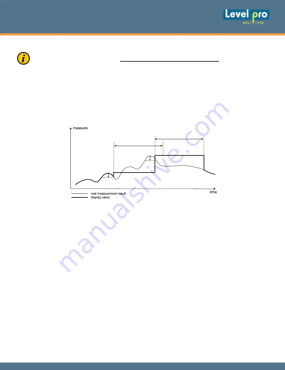
peak detection function. It can detect
the input
signal
peaks
and display their values. Presets connected with this function are placed in
“HOLd”
menu (see
description of
“HOLd”
menu).
6.2. DETECTION OF THE PEAK VALUES
Configuration of the device via menu
do
es
not
interrupt the
level
measure
ment
.
”timE”
”timE”
”PEA”
”PEA”
Figure 6.4. Process of peaks detection
Loop Powered Display
250 SERIES
09
The
250 Series
display
is equipped with one bistable SPDT relay output.
When energized it will LED
'R' will light up
.
It
is
no
t
possible
to change relay state
until
after
10 seconds
has
elapsed since
the
device
has been
power
ed
on.
The display must be powered
by at least 3.5 mA current.
After the
display is properly powered the change of relay state is four (4) seconds.
During device power off the
relay is set according to the value of
“AL”
parameter.
The different m
odes of the control can be changed
and are dependent
on the
parameter values for
“SEtP”
,
“SEt2”
,
“HYSt”
,
“modE”
and
“AL”
.
The
“modE”
parameter
will also the
relay
to
be used or
controlled over one or two thresholds values. If one threshold is used (figure 6.4) the relay can be
turned on (
“modE”
=
“on”
) or off (
“modE”
=
“oFF”
) when the input signal value enters the zone A. If
two thresholds are used (figure 6.5) the relay will be turned on when value of input signal enters the
zone A (
“modE”
=
“in”
) or zone B (
“modE”
=
“out”
) and turned off if the signal enters the second
one.
6.3. CONTROL OF THE RELAY OUTPUT


