background image

6


I

D E N T I F Y I N G  

E

X T E R N A L  

C

O M P O N E N T S


This chapter describes the front panel, rear panel and LED 
indicators of the Switch. 

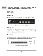
GSW-0506 

Front Panel 

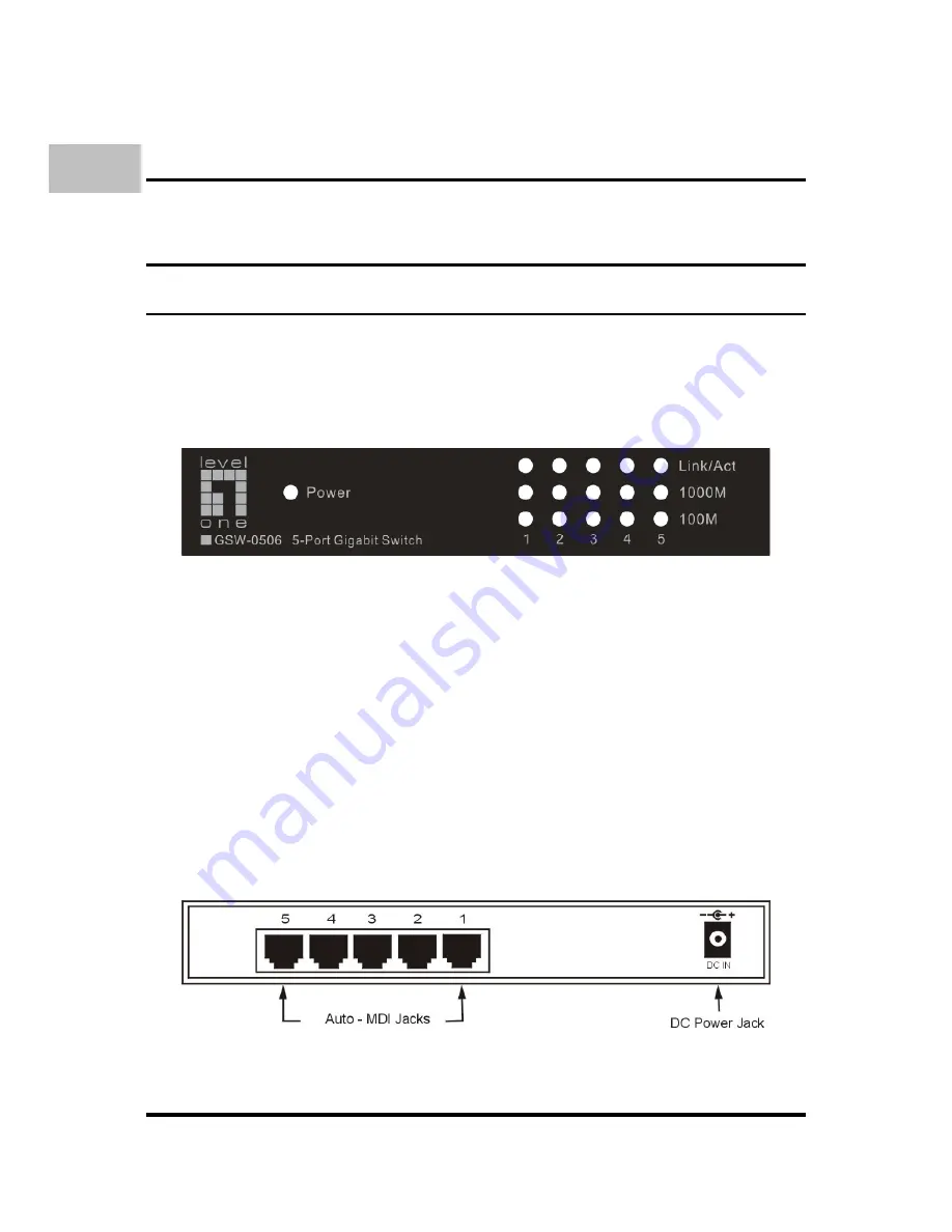
The figure below shows the front panels of the switch.


Front panel view of the Switch 

LED Indicators 

Comprehensive LED indicators display the conditions of the 
Switch and status of the network. A description of these LED 
indicators follows (see LED Indicators).


Rear Panel 

The rear panel of the Switch consists of an DC power connector. 
The following figure shows the rear panel of the Switch. 


Rear panel view of the Switch 

English 

Summary of Contents for GSW-0506

Page 1: ...LevelOne GSW 0506 GSW 0806 5 8 Port Gigabit Switch User Manual Benutzerhandbuch Version 1 0 0603...

Page 2: ......

Page 3: ...s uses and can radiate radio frequency energy and if not installed and used in accordance with this user s guide may cause harmful interference to radio communications Operation of this equipment in a...

Page 4: ......

Page 5: ...abit Switch and switch first letter lower case to refer to all Ethernet switches including the GSW 0506 0806 5 8 Port Gigabit Switch Overview of this User Manual Introduction Describes the Switch and...

Page 6: ...t provides a straightforward upgrade without wasting a company s existing investment in hardware software and trained personnel The increased speed and extra bandwidth offered by Gigabit Ethernet is e...

Page 7: ...nto different segments which don t compete with each other for network transmission capacity giving a decreased load on each The switch acts as a high speed selective bridge between the individual seg...

Page 8: ...in an environment where traffic on the network and the number of users increase continuously 5 8 port 10 100 1000 Mbps Gigabit Switch Conforms to IEEE 802 3 802 3u 802 3ab and 802 3x Auto MDIX on all...

Page 9: ...please contact your local reseller for replacement Setup The setup of the Switch can be performed using the following steps Install the Switch in a fairly cool and dry place See Technical Specificati...

Page 10: ...the switch Front panel view of the Switch LED Indicators Comprehensive LED indicators display the conditions of the Switch and status of the network A description of these LED indicators follows see L...

Page 11: ...ation of each indicator Power This indicator lights green when the Switch is receiving power otherwise it is off Link Act These LED indicators are lighted up when there is a secure connection or link...

Page 12: ...ont panel view of the Switch LED Indicators Comprehensive LED indicators display the conditions of the Switch and status of the network A description of these LED indicators follows see LED Indicators...

Page 13: ...ights green when the Switch is receiving power otherwise it is off Link Act These LED indicators are lighted up when there is a secure connection or link to the desired port The LED indicators blinkin...

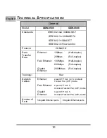
Page 14: ...x Ethernet 20Mbps Full duplex 100Mbps Half duplex Fast Ethernet 200Mbps Full duplex Gigabit Ethernet 2000Mbps Full duplex Topology Star Network Cables Ethernet 2 pair UTP Cat 3 4 5 Unshield Twisted Pa...

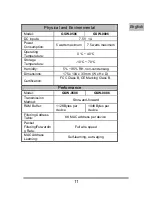
Page 15: ...ty 5 95 RH non condensing Dimensions 175 x 104 x 33 mm W x H x D Certification FCC Class B CE Marking Class B Performance Model GSW 0506 GSW 0806 Transmission Method Store and forward RAM Buffer 112KB...

Page 16: ...12...

Page 17: ...13 BER DIESE ANLEITUNG Diese Anleitung wird ihnen erkl ren wir Sie ihren GSW 0506 0806 5 8 Port Gigabit Switch mit ihrem Gigabit Ethernet Netzwerk verbinden Deutsch...

Page 18: ...Performance konzipiert 5 8 port 10 100 1000 Mbps Gigabit Switch Entspricht IEEE 802 3 802 3u 802 3ab und 802 3x Auto MDIX an allen Ports 10 16 Gbps back plane N Way Auto Negotiation Back pressure Half...

Page 19: ...t ist kontaktieren Sie bitte ihren H ndler Einrichtung Die Einrichtungs des Switches geschieht mit folgenden Schritten Installieren Sie den Switch an einen trockenen und k hlen Platz Installieren Sie...

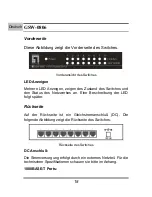
Page 20: ...seite des Switches Vorderansicht des Switches LED Anzeigen Mehrere LED Anzeigen zeigen des Zustand des Switches und den Status des Netzwerkes an Eine Beschreibung der LED folgt sp ter R ckseite Auf de...

Page 21: ...Power Diese Anzeige leuchtet gr n wenn der Switch Stom bekommt andernfalls ist sie aus Link Act Diese LED leuchtet wenn eine Verbindung zum entsprechenden Port hergestellt ist Die LED blinkt wenn Date...

Page 22: ...s und den Status des Netzwerkes an Eine Beschreibung der LED folgt sp ter R ckseite Auf der R ckseite ist ein Gleichstromanschlu DC Die folgende Abbildung zeigt die R ckseite des Switches R ckseite de...

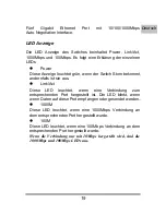
Page 23: ...lls ist sie aus Link Act Diese LED leuchtet wenn eine Verbindung zum entsprechenden Port hergestellt ist Die LED blinkt wenn wenn Daten auf diese Port empfangen oder gesendet werden 1000M Diese LED le...

Reviews: