background image

Page 3 of 6

PK-93776-10-02-0B

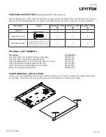
STANDARD ACCESSORIES 

(Included with Opt-X

®

 500i Enclosure)

Prior to installing your Leviton Opt-X

® 

500i Enclosure, please refer to the table below. This will help ensure that you 

have all the items shipped with the unit, and/or any additional items that may be required for proper installation.

Description 

Image 

Quantity in 1RU 

Kit

Quantity in 2RU 

Kit

Quantity in 3RU 

Kit

Cable Tie

4

4

4

Rack Mount Screw

4

4

4

Self Adhesive Label

2

2

2


OPTIONAL PART NUMBERS

Description 


Part Number

Universal Opt-X

®

 Clamp Kit for Enclosure Mounting  


5RCMP-KIT

Universal Opt-X

®

 Clamp Kit for Rack Mounting    


5RCMR-KIT

Fiber Cable Management 1/4 Ring Kit (bag of four 1/4 rings)  


5R100-14R

Opt-X

®

 500i Patch Cord Management Tray, 1RU   


5R1UL-CMT

Opt-X

®

 500i Patch Cord Management Tray, 2/3RU  


5R2UL-CMT

Splice Tray Mounting Hardware Kit 


SPLMT-HKT

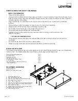
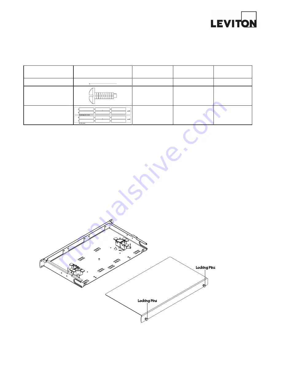
COVER REMOVAL / INSTALLATION

To remove cover: pull locking pins to unlock, and then slide cover to the rear. To install cover: assure locking pins

are unlocked , then slide cover onto the enclosure and push locking pin to latch cover in place.

Locking Pins

Locking Pins

Summary of Contents for Opt-X 500i

Page 1: ...ch Support 1 800 824 3005 E mail appeng leviton com Web www leviton com Copyright 2011 Leviton Manufacturing Co Inc All rights reserved Subject to change without notice MTP is a registered trademark of US Conec Ltd Page 1 of 6 PK 93776 10 02 0B 5R1UL F03 5R2UL F06 5R3UL F12 5R1UL F03 5R2UL F06 5R3UL F12 ...

Page 2: ... oil and debris Do not lay ferrule dust covers on a dirty or dusty surface Always use proper tools and or accessories to terminate fibers and clean connector tips QUICK START GUIDE The following instructions will help you quickly install your Leviton Opt X 500i Enclosure for use in your equipment cabinet or rack For detailed information on each step go to the page number listed below Safety and In...

Page 3: ...Label 2 2 2 OPTIONAL PART NUMBERS Description Part Number Universal Opt X Clamp Kit for Enclosure Mounting 5RCMP KIT Universal Opt X Clamp Kit for Rack Mounting 5RCMR KIT Fiber Cable Management 1 4 Ring Kit bag of four 1 4 rings 5R100 14R Opt X 500i Patch Cord Management Tray 1RU 5R1UL CMT Opt X 500i Patch Cord Management Tray 2 3RU 5R2UL CMT Splice Tray Mounting Hardware Kit SPLMT HKT COVER REMOV...

Page 4: ...apter No of Ports Number Scheme Duplex SC 3 pack 6 1 2 3 4 5 6 Duplex SC 6 pack 12 3 4 7 8 11 12 1 2 5 6 9 10 Duplex LC 6 pack 12 2 4 6 8 10 12 1 3 5 7 9 11 Quad LC 6 pack 24 5 6 7 8 13 14 15 16 21 22 23 24 1 2 3 4 9 10 11 12 17 18 19 20 ST FC 6 pack 6 1 2 3 4 5 6 ST FC 8 pack 8 1 2 3 4 5 6 7 8 Label Printing Organization by Fiber Adapter Type 3 RU Adapter Duplex SC 3 pack Duplex SC 6 pack Duplex ...

Page 5: ... into the slot of the right unit HALF RING INSTALLATION Position ring unit over outer ring slots so the alignment tabs fit into slots Press down and turn the ring unit clock wise to engage tabs and lock into position CAUTION when installing into a tray that is in the enclosure provide adequate support under the tray by placing a hand under the ring slot area FULL RING ASSEMBLY Hold a ring unit in ...

Page 6: ...IONS Typical installations not specific to enclosure Utilizing MTP Cassettes Utilizing Splice Trays Utilizing Fan Out Kits Utilizing Pre Terminated Cables or Field Termination of tight buffered cable Page 6 of 6 PK 93776 10 02 0B ...

Reviews: