background image


User Manual for BPS-i100 

www.levitronix.com 


PL-4036-00, Rev03, DCO# 21-057 


41


Troubleshooting 

7.1  Trouble Shooting with Stand-Alone Model 

For  troubleshooting  and  failure  analysis  with  the 

Stand-Alone

  model  the  integrated  display  gives  advice 

about status and potential failure details. 

If  the 

PLC


is used the digital output (“Status”) indicates if the system is active. However, the source of an 

error cannot be identified by this signal 


7.2  Trouble Shooting with EasyConnect and OEM Models 

7.2.1  Troubleshooting for Operation with Driver 

The integrated 

PLC 

provides a 

Status

 and 

Error

 signal feedback according to 

Table 15

. However, the source 

of error cannot be identified by these signals. 

For  more  detailed  analysis  the 

Levitronix

  Service  Software

  can  be  used  with  a  PC  and  a  USB  to  RS485 

interface cable. 

7.2.2  Troubleshooting with Levitronix

®

 Service Software 

The 

Levitronix

 Service Software

 allows communication with the pump system in connection with a PC and a 

USB  interface.  The  USB  to  RS485  adaptor  cable  as  specified  in 

Table  3 

can  be  used  to  setup 

communication. The software can be used for performing detailed troubleshooting.  

7.2.3  Troubleshooting with User Panel LUI-B.1 

For troubleshooting and failure analysis with the user panel

 LUI-B.1

 the integrated display gives advice about 

status and potential failure details. 


Technical Support 

For  troubleshooting,  support  and  detailed  technical  information  contact 

Levitronix


Technical  Service 

Department


Levitronix


Technical Service Department 

Technoparkstr. 1 
CH-8005 Zurich 
Switzerland 
 
Phone for US:          888-569 07 18 
Phone for outside US:    +1 888-569 07 18 
E-Mail:                TechSupport@levitronix.com 


Summary of Contents for BPS-i100

Page 1: ...e installation operation adjustment inspection and maintenance For special configurations of the pump system refer to accompanying information If the pump system must be configured for other parameter settings then the Levitronix Service Software version V2 0 5 0 or higher with relevant manual Levitronix Doc PL 4043 00 is necessary Familiarize yourself with the contents of the manual to ensure the...

Page 2: ...ion of RS485 Fieldbus Multi Pump System Arrays 27 4 2 7 Installation of Fieldbus for Serial Pumping 27 4 3 Electrical Installation of OEM Model 28 4 3 1 Overview Wire Designation of Driver Cable 28 4 3 2 Overview Electrical Schematics of Driver Interface 29 4 3 3 Installation Instructions for Power Supply 30 4 3 4 Installation PLC Interface Signals 30 4 3 5 Installation of RS485 Interface 30 4 3 6...

Page 3: ...rom computers monitors and all magnetic data storage media e g disks credit cards audio and video tapes etc WARNING Hazardous voltage may be present In case of the usage of an inadequate AC DC power supply mains voltages may be present even if the system is designed for up to 24 VDC The usage of a galvanic separated power supply which is certified by a 3rd party UL or CE is highly recommended Do n...

Page 4: ...O 21 057 4 2 Specifications 2 1 Specification of Components Figure 1 Pump system with main standard components Figure 2 Accessories Figure 3 Cables and cable accessories 4a 3 4b 4c 2b 1 B 2a 2d 2c 2e 1 2f D E 8 A 6 7b C 12 11 7a B 10 9c C D 9b F 9a E 9d A 13 A B 5 ...

Page 5: ...e 24VDC 160W 85 264 VAC 47 63 Hz 175 x 72 x 35 mm UL60950 1 CSA C22 2 TUV EN60950 1 Connector for direct connection to supply of driver cable length 1 2 m 4c AC Mains Cables AMC 1 1 2m AMC 1 2 2 5m AMC 1 3 AMC 1 4 2 5m AMC 1 5 2 5m 190 10331 32 190 10333 34 190 10335 Country Country Country US Canada CB Germ Den Norw Finl Belg Neth Sweden Austria PSE Japan Switzerland CE United Kingdom 5 USB to RS...

Page 6: ...low or pressure control Figure 5 Standard system configuration for EasyConnect model Integrated Pump Driver Stand Alone Model Power Supply Connector Pump Head Outlet Inlet PLC Connector Option for Remote Control with PLC Signals Desktop AC DC Power Supply AC Input DC Output Back Side Display with 3 Button User Interface for Speed Setting and Reading IPS Cable Signal Screw type connector for open w...

Page 7: ...ntrol Integrated Pump Driver EasyConnect Model 1 Pump Head Outlet Inlet Power Supply PLC Fieldbus OUT Fieldbus IN IPS Cable Signal Integrated Pump Driver EasyConnect Model 2 Pump Head Power Supply PLC Fieldbus OUT Fieldbus IN Integrated Pump Driver EasyConnect Model 3 Pump Head Power Supply PLC Fieldbus OUT Fieldbus IN IPS Cable Signal 24 VDC Supply 24 VDC Supply 24 VDC Supply IPS Cable Power Remo...

Page 8: ... s Remote Control AC DC Power Supply 24VDC DIN Rail AC Input DC Output PC Connection System configuration Service and Firmware update Monitoring Open Wires Fieldbus Interface Remote control with fieldbus Connection to PC Screw type connector for open wires connection included in converter cable package Fieldbus RS485 of Driver Integrated Driver Cable Cable Bushing Sensor Feedback for Flow or Press...

Page 9: ...e mains supply Surge immunity according to EN 61000 4 5 tested together with certified AC DC power supply Pollution degree 2 Table 4 Environmental conditions for pump system Note 1 Contact Levitronix technical department see Section 8 for outdoor usage Integrated Ex Pump Driver OEM Model Pump Head Outlet Inlet PLC Interface Analog and Digital IO s Remote Control AC DC Power Supply 24VDC DIN Rail A...

Page 10: ... 00 2 25 0 0 2 5 5 0 7 5 10 0 12 5 15 0 17 5 20 0 gallons min psi bar liters min 9000 rpm 4000 rpm Specific gravity 1 g cm3 Viscosity 0 7 cP Liquid Temp 40 C 8000 rpm 7000 rpm 6000 rpm 5000 rpm 0 20 40 60 80 100 77 87 97 107 117 127 137 147 157 167 177 187 0 1 2 3 4 5 6 7 8 25 30 35 40 45 50 55 60 65 70 75 80 85 90 psi F bar Liquid Temperature in C Max Operational Pressure for LPP 200 7 Max Static...

Page 11: ... Basic dimensions of Stand Alone model Figure 14 Basic dimensions and description of standard EasyConnect models 2e 1 Pump Head LPP 200 7 Driver IPD 100 6 Epoxy Coating Protective Cover for PLC Connector Included in driver package 2c 1 2d Pump Head Inlet and Outlet Fitting Tube 1 2 Pump Head Inlet and Outlet Fitting Tube 1 2 ...

Page 12: ...ication drawing 2a 1 Pump Head LPP 200 7 Driver IPD 100 1 Epoxy Coating Driver Cable PVC with Open Wires 2b 1 Driver IPD 100 2 ETFE Coating Driver Cable FEP with Open Wires 2f Driver IPD 100 10 ETFE Coating ATEX IECEx Pump Head Inlet and Outlet Fitting Tube 1 2 6pcs M4x16 Screws SS PTFE coated torque spec 20 Ncm For inner pump housing Tube 8pcs M3x40 Screws SS PTFE coated torque spec 15 Ncm For pu...

Page 13: ...e 1 Dimensions are in context with driver IPD 100 1 and pump head LPP 200 7 Note 2 Non tolerated dimensions are for reference only Note 3 For other configurations refer to according drawings NPT 1 8 x 6 7 mm In outlet for water cooling fittings Mounting Screws 2x M4x16mm Inox A4 PTFE coated Torque 50 cNm Note remove 2 motor screws before mounting WCM 100 ...

Page 14: ...n Minimum Bending Radius Sometimes Moved FEP 8 mm 7x Cable OD 15 x Cable OD PVC 8 4 mm 7x Cable OD 15 x Cable OD Table 5 Specifications for min bending radius of driver cable Note If not mentioned explicitly all the cables are not suited for constant dynamic bending and movement to AC DC Supply to driver DC supply 6 to driver fieldbus IN 7a to driver fieldbus OUT 7b to external interface EasyConne...

Page 15: ...nless steel PTFE coated screws 5 Impeller LPI 200 5 PFA 6 Rotor magnet encapsulated Rare earth material 7 8 pcs M3 x 40 mm for pump motor mounting SS stainless steel PTFE coated screws Driver IPD 100 1 50 Epoxy PVC IPD 100 2 50 ETFE FEP 8 Sealing O ring and gasket for motor housing FPM FKM 9 Cable bushing Cable material PVDF housing with FPM sealing PVC or FEP cable jacket 10 Driver housing Epoxy ...

Page 16: ... than the standard specified ones are used it is recommended to evaluate them under demanding operating situations like fast braking from maximum speed and during power on and take off of the impeller 3 3 Temperature Monitoring To avoid overheating of the system the controller and motor temperatures within the driver are monitored If one of both temperatures exceeds 80 C 176 F for a duration of mo...

Page 17: ... values which are partly based on measurements and partly on interpolations with a simplified thermal model and are therefore only guideline values and are suitable for a first layout of the basic thermal concept It is recommended to check the thermal values with the motor placed on the final location and under worst case performance conditions of the application To account for thermal variations ...

Page 18: ...0 0 2 5 5 0 7 5 10 0 12 5 15 0 17 5 20 0 F gallons min C liters min Absolute Temperature Limit Recommended Operational Temperature Limit 5000 rpm 6000 rpm 7000 rpm 8000 rpm 9000 rpm 4000 rpm Specific gravity 1 g cm3 Viscosity 0 7 cP Ambient Temp 25 C 77 97 117 137 157 177 0 0 1 0 2 0 3 0 4 0 5 0 25 35 45 55 65 75 85 0 0 2 5 5 0 7 5 10 0 12 5 15 0 17 5 20 0 F gallons min C liters min Absolute Tempe...

Page 19: ...e inlet pressure of the pump head and minimized heat up of the liquid 6 In general the pump system placement and circuit shall be designed in a way that gas bubbles can leave the pump housing and that the pump head remains primed 7 To minimize heat up of the liquid the overall pressure drop in the hydraulic circuit shall be reduced as much as possible 8 It shall be avoided to pump longer times aga...

Page 20: ...in Name Wire Color 1 Description Standard Designation 2 Typical Levels Note 6 Ain1 pink Analog Input Remote Speed 4 20 mA 0 10000 rpm Speed limit 9000rpm Cut off min speed 0 rpm 450 Ohm shunt input no galvanic isolation blue 5 Ain_GND red Analog Input Ground Reference to Ain1 1 Dout1 white Digital Output Status Closed circuit active system on Open circuit not active system off Open drain max 24V 1...

Page 21: ...cuit Example of User Interface Circuit 450 2 2 k Pin 1 Digital Output Pin 4 Common Digital Input Pin 2 Digital Input Pin 5 Analog Input Ground Pin 6 Analog Input Pin 3 Ground GND Pin 3 Cable Shield Analog inputs are not galvanic isolated Max pin voltage to GND 10 V Max 24 V 100 mA Open Drain R 240 Relais AC DC Supply 24 VDC Pin 2 Power 24 VDC Pin 1 Power Ground Earth 30 V 5 24 V 4 20 mA GND GND 24...

Page 22: ...supplies with smaller power or bigger supplies to supply several pump systems simultaneously may be used Consult Figure 20 to get the power consumption depending on the flow If other power supplies are used than the one recommended by Levitronix it is highly recommended to test these under dynamic conditions acceleration and braking of the pump rotor speed 3 Make sure that the polarity is correct ...

Page 23: ...remote control with other devices Usage of Levitronix Service Software with a RS485 to USB adaptor cable 2 RS485 yellow RS485 4 Internal grey Internal Do not connect Internal bus needed to connect pumps for serial pumping 5 Internal red Internal Table 11 Fieldbus IN connector of EasyConnect driver 1 Wires of compatible cables ICS 1 1 xx and ICS 1 2 xx Pin Pin Name Wire Color 1 Description Standard...

Page 24: ...max 24V 100mA This signal indicates the state of the pump system The configuration of the digital outputs can be changed with Levitronix Service Software 1 Dout2 white Digital Output Error Closed circuit not active system ok Open circuit active system error Open drain max 24V 100mA When active the system drives the impeller to zero rpm and shuts down With a reset pulse see Enable description the s...

Page 25: ... Ground Pin 7 Analog Input 1 Pin 8 Analog Input 2 Pin 10 Ground GND Pin 9 Analog Output Pin 1 RS485 Pin 2 RS485 Pin 4 Do not connect Pin 5 Do not connect Pin 3 Ground Relais GND 4 20 mA 0 10 V 2 mA 24 V 5 24 V 0 10 V R 5 k Analog inputs are not galvanic isolated Max pin voltage to GND 10 V Max 24 V 100 mA Max 24 V 100 mA Open Drain Open Drain R 240 R 240 Relais R 510 Tool Control R 510 AC DC Suppl...

Page 26: ...is correct and that AC DC power supply is off 4 2 4 Installation PLC Interface Signals To operate the pump system with a PLC the analog input can be used to set either the speed or the process value flow or pressure The digital and analog outputs can be used to monitor the pump status and operating parameters see Table 13 CAUTION The analog input is not galvanically isolated from the controller el...

Page 27: ...ieldbus array must be terminated as illustrated in Figure 29 A dedicated connector with integrated termination resistor see Table 3 is available The RS485 protocol for master communication is available at Levitronix on request Do not use multiple master systems at the same time and do not use closed ring arrangements 4 2 7 Installation of Fieldbus for Serial Pumping Serial pumping setup with up to...

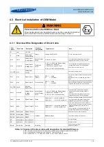
Page 28: ...OM yellow Common Digital Input Aout1 blue red Analog Output Voltage Output Actual Speed Actual Process Value 0 10 V 0 10000 rpm Speed Mode Speed limit 9000rpm 9 V 0 10 V 0 100 Process Mode Direct connection no protection Galvanic isolation on user side is required AGND is reference The configuration of the analog output can be changed with Levitronix Service Software Dout1 brown Digital Output 1 S...

Page 29: ...Output 2 Yellow Common Digital Input Grey Digital Input 2 Pink Digital Input 1 Blue Analog Input Ground Violet Analog Input 1 Grey Pink Analog Input 2 White Green Analog Ground GND Blue Red Analog Output Brown Green RS485 White Yellow RS485 Yellow Brown Do not connect White Grey Do not connect Cable Shield Relais GND 4 20 mA 0 10 V 2 mA RS485 USB Cable with Termination Personal Computer Service 24...

Page 30: ...operate the pump system with a PLC the analog input can be used to set either the speed or the process value flow or pressure The digital and analog outputs can be used to monitor the pump status and operating parameters see Table 14 CAUTION The analog inputs and outputs are not galvanic isolated from the controller electronics To avoid ground loops and mal functions use floating analog signals 1 ...

Page 31: ...e time Do not use closed ring arrangements 4 4 Mechanical Installation General Instructions WARNING Standard pump drivers are not rated to be placed next to flammable gases Do not use the driver next to flammable gases without adequate safety precautions to fulfill the relevant regulatory requirements WARNING Only specific pump drivers are classified for the use in Ex classified locations Refer to...

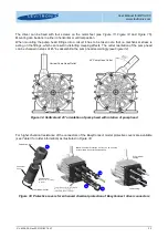
Page 32: ...s of 45 by assembling the pump head accordingly see Figure 32 Figure 32 Vertical and 45 orientation of pump head with rotation of pump head For higher chemical resistance of the connectors of the EasyConnect model protective covers are available see Table 3 for order information as illustrated in Figure 33 Figure 33 Protective covers for enhanced chemical protection of EasyConnect driver connector...

Page 33: ...ne model for manual operation 5 1 2 Operation with PLC When activating the digital input on the PLC connector the speed can be set with an analog signal see Table 9 for hardware details The Status of the system can be monitored with a digital output signal During analog speed control all information is shown on the display 5 1 3 Extended Menu Functions By pressing the On Off button for more than 4...

Page 34: ...enu tabs 1 Set Speed control Mode Button à Analog In Auto start Off à On select with change values with 2 Set Timer Mode Off à Single à Repeat Time hh mm ss select with change values with 3 Read system information Temperature Axial position DC link voltage 4 Read system information BNG currents DRV currents 5 Read actual errors warnings and messages 6 Read history of errors warnings and messages 7...

Page 35: ...ff button or by a pulse of 300 700ms on the digital input of the PLC interface see Table 9 Menu The Menu is not a system state but an additional tool to modify the system setup or to display system information From any system state the menu is reached pushing the On Off button for more than 4 seconds and left by pushing it for more than 2 seconds The following menu points are available Menu Tab 1 ...

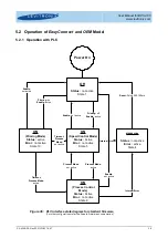
Page 36: ... 1 Power On ON Speed Control Mode Status Active Error not active State 5 ERROR Status not active Error active State 4 Priming off Enable active Reset Pulse 300 700 ms ON Process Control Mode Status Active Error not active State 6 Internal Error Internal Error Enable not active Process Mode active Process Mode not active ON Priming Mode Status active Error not active State 10 Priming on Enable acti...

Page 37: ...nput the system gets back to the Off state Errors Effect on Designated Digital Output of the PLC No rotor Error Open circuit Temperature over 90 C Error Open circuit Temp was higher than 80 C for more than 10 minutes Error Open circuit Over current Error Open circuit Power channel interrupted Error Open circuit Internal sensor cable interrupted Error Open circuit DC link supply voltage out of rang...

Page 38: ...ng issues Pump head must completely be filled with liquid prior to enabling and operation of the pump CAUTION The user shall prevent friction on driver and on pump head surfaces as to avoid electrostatic charges during system operation CAUTION The user shall prevent electrostatic charging of the system at cleaning processes by using dry cleaning cloth User shall use wet cleaning rags to avoid issu...

Page 39: ...re 37 Explosion view of pump head with driver Figure 38 Components for impeller replacement The following warnings and cautions should be read carefully before starting the replacement of the impeller WARNING The impeller could splash TOXIC or CORROSIVE CHEMICALS because of the strong magnetic forces Flush the pump housing before opening it WARNING HARMFUL CHEMICALS may be present Skin contact and...

Page 40: ...lid of the pump casing CAUTION Use always the specified O Ring type If necessary consult the Levitronix Technical Service Depart ment Do NOT twist or roll the O Ring and avoid to adding scratches or particles as this may cause leaking to occur 7 Press the lid with the O Ring flush into the bottom of the pump casing 8 Carefully tighten the 6 pump head screws The screws should not be used to press t...

Page 41: ...vitronix Service Software can be used with a PC and a USB to RS485 interface cable 7 2 2 Troubleshooting with Levitronix Service Software The Levitronix Service Software allows communication with the pump system in connection with a PC and a USB interface The USB to RS485 adaptor cable as specified in Table 3 can be used to setup communication The software can be used for performing detailed troub...

Page 42: ...ty with the requirements of the Directive 2014 34EU and the applicable IEC standards The following standards are tested and confirmed at a certified laboratory IEC EN 60079 0 Explosive atmospheres General requirements IEC EN 60079 7 Explosive atmospheres Equipment protection by increased safety e IEC EN 60079 18 Explosive atmospheres Equipment protection by encapsulation m IEC EN 60079 31 Explosiv...

Page 43: ...not avoided could result in property damage Signal word SEMI S1 0701 Safety alert for Warning and Caution Safety alert SEMI S1 0701 Safety alert for Danger Safety alert SEMI S1 0701 Caution refer to accompanying documents is used on article labels for reference to manual Refer to manual ISO 3864 Toxic material poison Hazard identification IEC 61310 Corrosive material corrosion Hazard identificatio...

Reviews: