User Manual for PuraLev
®
600MU
www.levitronix.com
PL-4033-00, Rev09, DCO# 20-144
26
4.2 Mechanical Installation of the Pump/Motor
•
T
he motor can be fixed with four screws on the motor feet (see
).
•
As an alternative the motor can be mounted with four screws on the backside (see
).
•
The motor can be mounted in either horizontal or vertical position.
•
Each motor is identified with a unique serial number. This serial number consists of a series of
6 digits were the 5
th
and the 6
th
digit representing the manufacturing year.
4.3 Mechanical Installation of ATEX / IECEx Motors
!
WARNING
Only specific types of motors LPM-600 are classified for the use in
ATEX Zone 2 classified locations. Refer to the corresponding section in
the manual.
!
WARNING
Cable and cable glands of the motor must be protected against impact
energy.
!
WARNING
Motors for ATEX / IECEx applications. Use only, if necessary, the
cooling module ACM-600.3 for motors installed in Ex classified
locations. The use of other materials for the air cooling module is not
allowed.
An
Ex
conform solution is needed for the motor cables to leave the
ATEX
and
).
One option is an
ATEX
certified cable system as listed in
A protective earth wire (min. AWG 14, copper cross section 2.08 mm
2
) shall be attached to the
ATEX / IECEx
specific motor housings by using one of the four M5 threads on the backside of the motor
by following the
instructions outlined below.
1) Motors used without air cooling module ACM-600.3
•
Remove one of the four M5 screws on the backside of the motor.
•
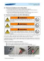
Use a crimp-type end together with a spacer sleeve to connect an earth wire.
•
Attach the earth wire with a M5 stainless steel screw to the motor according to Figure 31.
Figure 31: Attachment of a protective earth wire to the backside of the motor
(Screw dimensions: M5 x 15 mm, spacer dimensions: OD = 9 mm, ID = 6 mm, length = 6 mm)


