User Manual for PuraLev
®
600MU
www.levitronix.com
PL-4033-00, Rev09, DCO# 20-144
28
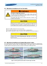
4.4 Mechanical Installation of the Controller
!
WARNING
Hazardous voltage may be present.
In order to avoid fluid spills shorting mains or other voltages within the
controller, place the controller in a spill protected environment (for
example protected electronic cabinets).
If explosive flammable gases are present, place the controller in an
explosion-proof cabinet.
CAUTION
Make sure the controller is mounted in a position that allows free air
circulation around the controller. A minimum distance of 10cm
(4”) to
other objects above or below the controller casing is recommended.
•
Use the DIN-rail bracket to mount the controller.
•
If no forced air-cooling is used, mount the controller in upright position.
•
The DIN-rail brackets can also be mounted on the controller side according to
CAUTION
Use only 3.5 x 6.5 mm self-tapping screw for the fixation of the DIN-rail
brackets.
The controller may be damaged if other type or too long screw
types are used!
4.5 Mechanical Installation of Adaptor/Extension Cables
For connecting the motor to the controller the adaptor cables
MCAP-600.x
(for power cable) and
MCAS-600.x
(for sensor cable) are used (see
for adaptor cables). For the cables which use an M23 threaded
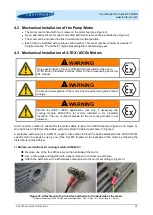
metallic Hummel connector type, check the connection according to the following pictures:
Figure 33: Wrong and correct Hummel connector type assembly
O-Ring visible
Wrong Connection!
O-Ring not visible
Correct Connection!
Gap > 2 mm
Sensor Cable
of Motor
Power Cable
of Motor
Gap > 1 mm
Gap
1 mm
Gap
2 mm
Sensor
Adaptor Cable
Power
Adaptor Cable


