User Manual for PuraLev
®
i100SU
www.levitronix.com
PL-4063-00, Rev03, DCO# 20-275
19
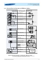
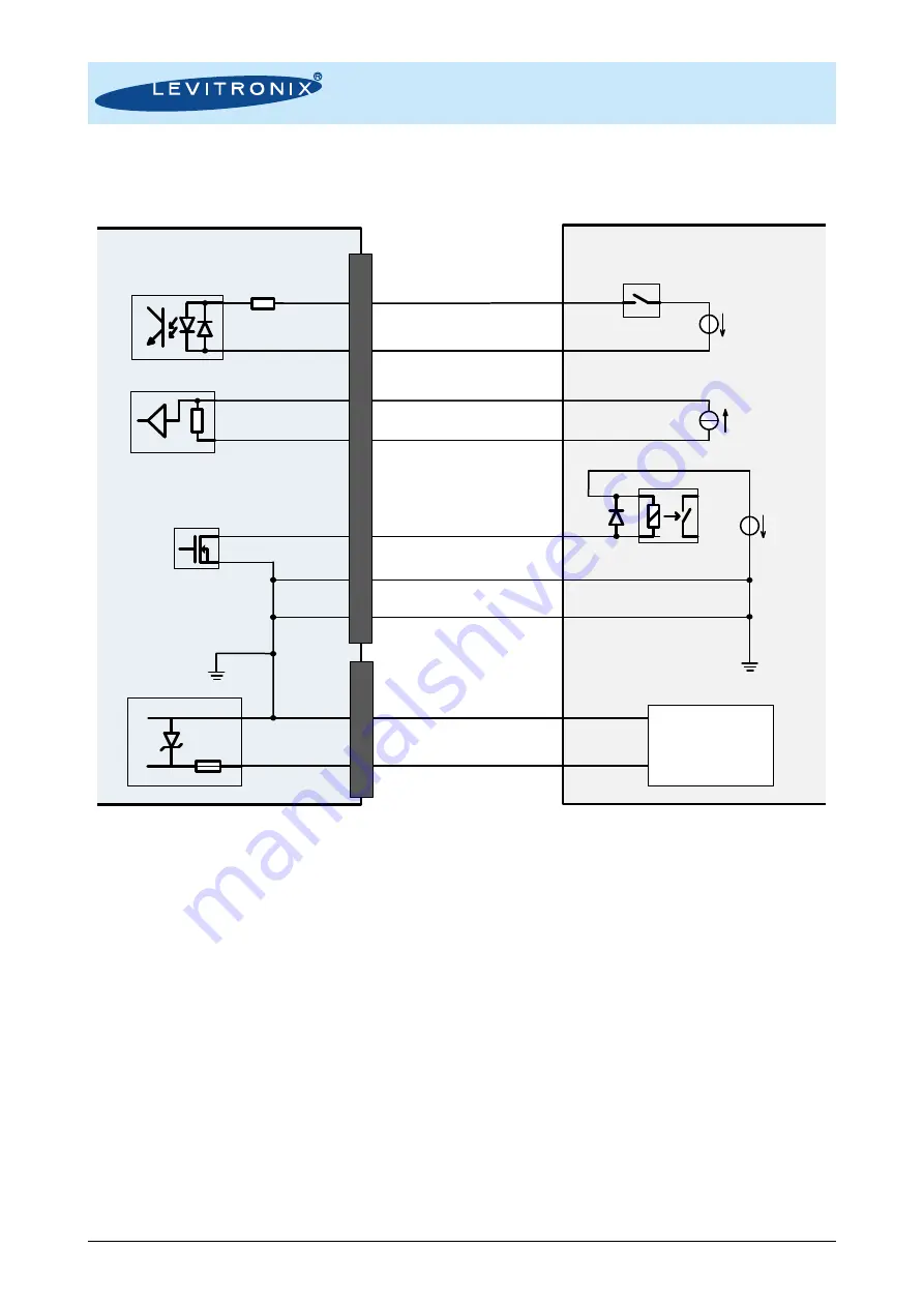
4.1.2 Overview Electrical Schematics of Stand-Alone Driver Interface
Figure 21: Electrical schematics of interfacing for Stand-Alone driver model
Levitronix Driver
Interface Circuit
Example of User
Interface Circuit
450
2.2 k
Pin 1: Digital Output
Pin 4: Common Digital Input
Pin 2: Digital Input
Pin 5: Analog Input Ground
Pin 6: Analog Input
Pin 3: Ground (GND)
Pin 3: Cable Shield
Analog inputs are not galvanic isolated.
Max. pin voltage to GND = 10 V
Max. 24 V / 100 mA
Open
Drain
R > 240
Relais
AC/DC Supply
24 VDC
Pin 2: Power 24 VDC
Pin 1: Power Ground/Earth
30 V
5..24 V
4..20 mA
GND
GND
24 V
5 A
P
L
C
6
In
te
rf
a
c
e
P
o
w
e
r
S
u
p
p
ly
10 A


