background image


User Manual for PuraLev

®

 i100SU 

www.levitronix.com 


PL-4063-00, Rev03, DCO# 20-275 


38


6.3  Mounting of Pump Head 

6.3.1 

Preparation 

After removal of the pump head from its packaging 
assure  that  no  metallic  part  is  magnetically 
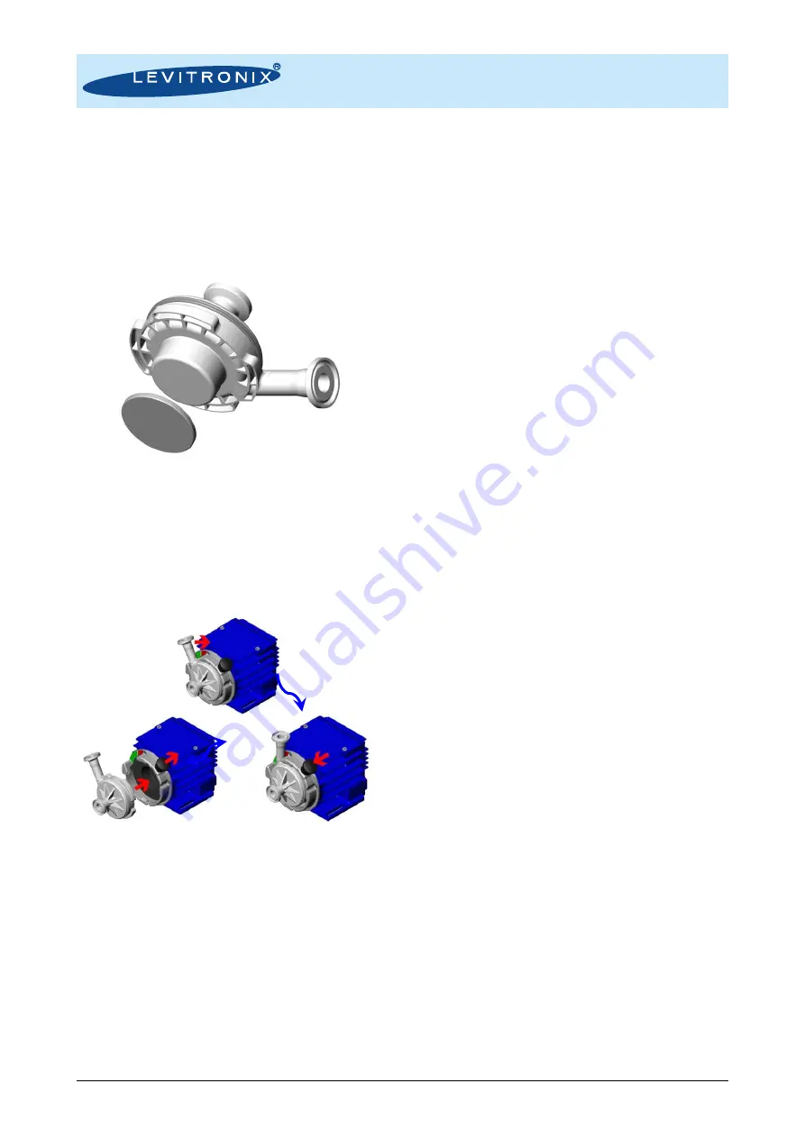
attaching.  Specifically  remove  the 

Fixation  Disc

which comes delivered within the packaging in order 
to magnetically fix the impeller against movements 
during transportation. 


Figure 33: Pump head with Fixation Disc 

Assure that the impeller speed is set to 0 rpm and 
that the system is disabled. 

6.3.2 

Step 1: Insertion 

Pull the 

Locking Pin

 radially outwards and insert the 

pump head at the same time. 


Figure 34: Intuitive 3-step pump head mounting  

procedure with bayonet type socket 

6.3.3 

Step 2: Rotation and Snap-In 

Smoothly rotate the pump head clockwise until the 

Locking Pin

 snaps in. 


6.3.4 

Step 3: Ready-to-Use Check 

Check  that  the 

Locking  Pin

  is  properly  snapped  in 

and  that  the  green  labeling  on  the 

Pump  Head 

Socket

, beside the outlet, is visible. 

6.4  Removal of Pump Head 

6.4.1 

Preparation 

Set the speed to 0 rpm and disable the system. After 
running  at  higher  motor  or  liquid  temperature  the 
pump head might stick to the motor due to thermal 
expansion effects. Let the system cool down before 
starting the removal procedure. 

6.4.2 

Step 1: Pull Pin and Rotate 

Pull the 

Locking Pin

 radially outwards and rotate the 

pump  head  smoothly  counterclockwise  as  far  as 
possible. 

6.4.3 

Step 2: Axial Removal 

Smoothly remove the pump head axially. 

6.4.4 

Step 3: Usage of Fixation Disc 

It is recommended to attach the 

Fixation Disc

 (see 

Figure  33

)  to  the  pump  head  bottom  in  order  to 

minimize  magnetic  leakage  fields  surrounding  the 
impeller and hence reducing the tendency to attract 
other magnetic parts. 


6.5  Assembly into Hydraulic Circuit 

The  following  points  shall  be  considered,  when 
integrating the pump head into a single-use circuit. 

6.5.1 

Usage of Fixation Disc 

During  handling,  assembling  and  transportation  of 
the  pump  head  with  the  hydraulic  circuit,  it  is 
recommended  to  attach  the 

Fixation  Disc

  (see 

Figure 33

) to the pump head bottom. The disc holds 

the impeller mechanically in place and reduces the 
magnetic  fields,  which  can  attract  other  magnetic 
parts 

during 

handling, 

sterilization 

and 

transportation. 

6.5.2 

Handling of Multiple Pump Heads 

Be  aware  of  the  magnetic  forces  of  the  impellers 
when  handling  multiple  pump  heads  at  the  same 
time. Avoid two pump heads coming together with 
force  due  to  the  magnetic  attraction,  which  might 
cause cracks. 

6.5.3 

Avoidance of Mechanical Stress 

Avoid applying too  much mechanical stress to the 
pump head for example, by excessively squeezing 
it with the other parts of the circuit to a packaging 
or  an  enclosed  space  of  limited  size,  or  by 
applying  too  much  tension  or  perpendicular  force 
to the fittings. 

Mounting  

Step 1:  

Insertion 

Mounting Step 2: Rotation 

Mounting Step 3: Ready-to-Use Check 

(Pin snapped in and green label visible) 


Fixation Disc 
(Ferro Magnetic) 

Pump Head 
DCP-200 

Summary of Contents for PuraLev i100SU

Page 1: ...ing its use installation operation adjustment inspection and maintenance For special configurations of the pump system refer to accompanying information If the pump system must be configured for other parameter settings then the Levitronix Service Software version V2 0 5 0 or higher with relevant manual Levitronix Doc PL 4043 00 is necessary Familiarize yourself with the contents of the manual to ...

Page 2: ...8 4 1 Electrical Installation of Stand Alone Model 18 4 2 Electrical Installation of EasyConnect Model 21 4 3 Electrical Installation of OEM Model 26 4 4 Mechanical Installation 30 5 OPERATION 31 5 1 Operation of Stand Alone Model 31 5 2 Operation of EasyConnect and OEM Model 34 5 3 Operation for ATEX IECEx Application 36 6 INSTRUCTIONS FOR USE OF PUMP HEAD 37 6 1 Description and Preparation 37 6 ...

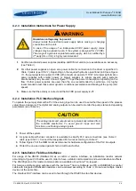
Page 3: ...distance from computers monitors and all magnetic data storage media e g disks credit cards audio and video tapes etc WARNING Hazardous voltage may be present In case of the usage of an inadequate AC DC power supply mains voltages may be present even if the system is designed for up to 24 VDC The usage of a galvanic separated power supply which is certified by a 3rd party UL or CE is highly recomm...

Page 4: ...0 Rev03 DCO 20 275 4 2 Specifications 2 1 Specification of Components Figure 1 Pump systems with standard components Figure 2 General standard accessories Figure 3 Standard cables 2a 2b 2c 5 A B C D 4a 4b 4c 10 6 7a 7b 8 9 11 B C D F E A 1a 3 1b 1e A B B C C 2d ...

Page 5: ...firmware available on request Note 3 CPC and AseptiQuik are registered marks of the Colder Product Company Pos Component Article Name Article Characteristics Value Feature 4a AC DC Power Supply TSP 180 124 Traco 100 40018 Voltage Output Input Basic Dimensions Certification or Standards 24 VDC with 180 W 85 132 and 187 264 VAC autoselect 110 x 110 x 54 mm mountable on DIN rail 35 mm UL cUL CB Semi ...

Page 6: ...nfiguration for EasyConnect model Integrated Pump Driver Stand Alone Model Power Supply Connector Single Use Pump Head Outlet Inlet PLC Connector Option for Remote Control with PLC Signals Back Side Display with 3 Button User Interface for Speed Setting and Reading IPS Cable Signal Screw type connector for open wires connection included in cable package Bayonet Socket with Locking Pin Power Supply...

Page 7: ...gure 7 System configuration of OEM model for speed control Integrated Pump Driver EasyConnect Model 1 Outlet Inlet Power Supply PLC Fieldbus OUT Fieldbus IN IPS Cable Signal Integrated Pump Driver EasyConnect Model 2 Power Supply PLC Fieldbus OUT Fieldbus IN Integrated Pump Driver EasyConnect Model 3 Power Supply PLC Fieldbus OUT Fieldbus IN IPS Cable Signal 24 VDC Supply 24 VDC Supply 24 VDC Supp...

Page 8: ...l AC DC Power Supply 24VDC DIN Rail AC Input DC Output PC Connection System configuration Firmware update Monitoring Open Wires Screw type connector for open wires connection included in converter cable package Integrated Driver Cable Cable Bushing Sensor Feedback for Flow or Pressure Control USB RS485 Converter Cable Flow or Pressure Sensor User Panel 24VDC Fieldbus RS485 Single Use Pump Head Bay...

Page 9: ...es typically present on the mains supply Surge immunity according to EN 61000 4 5 tested together with certified AC DC power supply Pollution degree 2 Table 4 Environmental conditions for pump system Integrated Ex Pump Driver OEM Model Outlet Inlet PLC Interface Analog and Digital IO s Remote Control AC DC Power Supply 24VDC DIN Rail AC Input DC Output PC Connection System configuration Service an...

Page 10: ...5 10 15 20 25 30 0 0 1 0 2 0 3 0 4 0 5 0 0 00 0 25 0 50 0 75 1 00 1 25 1 50 1 75 2 00 2 25 0 0 2 5 5 0 7 5 10 0 12 5 15 0 17 5 20 0 psi gallons min bar liters min Specific gravity 1 g cm3 Viscosity 0 7 cP Liquid Temp 40 C DC Voltage 24VDC Pumphead DCP 200 2 8000 rpm 7000 rpm 6000 rpm 5000 rpm 4000 rpm 9000 rpm 0 10 20 30 40 50 60 70 80 77 87 97 107 117 127 137 0 1 2 3 4 5 6 25 30 35 40 45 50 55 60...

Page 11: ...C Connector Included in driver Package 3 Pump Head Socket PHS i100 1 Locking Pin Note Pump Head Socket can be mounted and rotated in steps of 45 to change pump outlet orientation 2b Single Use Pump Head DCP 200 2 Driver IPD 100 4 Protective Cover Nut for PLC and Fieldbus Connectors Included in driver package 3 Pump Head Socket PHS i100 1 Locking Pin Note Pump Head Socket can be mounted and rotated...

Page 12: ...ent 2a Pump Head DCP 200 2 Driver IPD 100 1 Epoxy Coating Driver Cable PVC with Open Wires Pump Head Socket PHS i100 1 Note Pump head socket can be mounted and rotated in steps of 45 to change pump outlet orientation Inlet Outlet Fitting 1 2 Triclamp Clamp OD 25mm for Mini Clamp Bore ID 9 4 mm for 3 8 ID tubing Standard ASME BPE 2009 1a 2a Driver IPD 100 10 ATEX IECEx ETFE Coating Driver Cable FEP...

Page 13: ...rmanent Installation Minimum Bending Radius Sometimes Moved PVC 8 4 mm 7x Cable OD 15 x Cable OD Table 5 Specifications for min bending radius of cables Note If not mentioned explicitly all the cables are not suited for constant dynamic bending and movement to AC DC Supply to driver DC supply 6 to driver fieldbus IN 7a to driver fieldbus OUT 7b to external interface EasyConnect driver to fieldbus ...

Page 14: ...ower supplies than the standard specified ones are used it is recommended to evaluate them under demanding operating situations like fast braking from maximum speed and during power on and take off of the impeller 3 2 Temperature Monitoring To avoid overheating of the system the controller and motor temperatures within the driver are monitored If one of both temperatures exceeds 80 C 176 F for a p...

Page 15: ...d temperature Pumping with pump head DCP 200 temperature is measured inside of the integrated motor and controller contact temperature is below this temperature 77 97 117 137 157 177 0 0 1 0 2 0 3 0 4 0 5 0 25 35 45 55 65 75 85 0 0 2 5 5 0 7 5 10 0 12 5 15 0 17 5 20 0 F gallons min C liters min Ambient Temp 25 C Liquid Temp 25 C Specific gravity 1 g cm3 Viscosity 0 9 cP 9000 rpm 8000 rpm 7000 rpm ...

Page 16: ...tly on interpolations with a simplified thermal model and are therefore only guideline values and are suitable for a first layout of the basic thermal concept It is recommended to check the thermal values with the motor placed on the final location and under worst case performance conditions of the application In order to account for thermal variations like ambient temperature closed chemical cabi...

Page 17: ... loss 4 Place the pump at the lowest point of the hydraulic circuit Optimum is as much as possible below a tank or reservoir This optimizes priming behavior and keeps the inlet pressure positive for low shear forces 5 Keep the liquid level in the reservoir tank or bag as high as possible which increases the inlet pressure of the pump head and minimized heat up of the liquid 6 When horizontal mount...

Page 18: ...ation Pin Pin Name Wire Color 1 Description Standard Designation 2 Typical Levels Note 6 Ain1 pink Analog Input Remote Speed 4 20 mA 0 10000 rpm Speed limit 9000rpm Cut off min speed 0 rpm 450 Ohm shunt input no galvanic isolation blue 5 Ain_GND red Analog Input Ground Reference to Ain1 1 Dout1 white Digital Output Status Closed circuit active system on Open circuit not active system off Open drai...

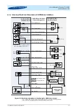
Page 19: ...rface Circuit Example of User Interface Circuit 450 2 2 k Pin 1 Digital Output Pin 4 Common Digital Input Pin 2 Digital Input Pin 5 Analog Input Ground Pin 6 Analog Input Pin 3 Ground GND Pin 3 Cable Shield Analog inputs are not galvanic isolated Max pin voltage to GND 10 V Max 24 V 100 mA Open Drain R 240 Relais AC DC Supply 24 VDC Pin 2 Power 24 VDC Pin 1 Power Ground Earth 30 V 5 24 V 4 20 mA G...

Page 20: ...er supplies with smaller power or bigger supplies to supply several pump systems simultaneously may be used Consult Figure 17 to get the power consumption depending on the flow If other power supplies are used than the one recommended by Levitronix it is highly recommended to test these under dynamic conditions acceleration and braking of the pump rotor speed 3 Make sure that the polarity is corre...

Page 21: ...or remote control with other devices Usage of Levitronix Service Software with a RS485 to USB adaptor cable 2 RS485 yellow RS485 4 Internal grey Internal Do not connect Internal bus needed to connect pumps for serial pumping 5 Internal red Internal Table 10 Fieldbus IN connector of EasyConnect driver 1 Wires of compatible cables ICS 1 1 xx and ICS 1 2 xx Pin Pin Name Wire Color 1 Description Stand...

Page 22: ... off Open drain max 24V 100mA This signal indicates the state of the pump system The configuration of the digital outputs can be changed with Levitronix Service Software 1 Dout2 white Digital Output Error Closed circuit not active system on Open circuit active system off Open drain max 24V 100mA When active the system drives the impeller to zero rpm and shuts down With a reset pulse see Enable des...

Page 23: ...put Ground Pin 7 Analog Input 1 Pin 8 Analog Input 2 Pin 10 Ground GND Pin 9 Analog Output Pin 1 RS485 Pin 2 RS485 Pin 4 Do not connect Pin 5 Do not connect Pin 3 Ground Relais GND 4 20 mA 0 10 V 2 mA 24 V 5 24 V 0 10 V R 5 k Analog inputs are not galvanic isolated Max pin voltage to GND 10 V Max 24 V 100 mA Max 24 V 100 mA Open Drain Open Drain R 240 R 240 Relais R 510 Tool Control R 510 AC DC Su...

Page 24: ...ect and that AC DC power supply is off 4 2 4 Installation PLC Interface Signals To operate the pump system with a PLC the analog input can be used to set either the speed or the process value flow or pressure The digital and analog outputs can be used to monitor the pump status and operating parameters see Table 12 CAUTION The analog inputs and outputs are not galvanically isolated from the contro...

Page 25: ... must be terminated as illustrated in Figure 24 A dedicated connector with integrated termination resistor see Table 3 is available The RS485 protocol for master communication is available at Levitronix on request Do not use multiple master systems at the same time and do not use closed ring arrangements 4 2 7 Installation of Fieldbus for Serial Pumping Serial pumping setup with up to 3 pumps can ...

Page 26: ... Speed Actual Process Value 0 10 V 0 10000 rpm Speed Mode 0 10 V 0 100 Process Mode Direct connection no protection Galvanic isolation on user side is required AGND is reference The configuration of the analog output can be changed with Levitronix Service Software Dout1 brown Digital Output 1 Status Closed circuit active system on Open circuit not active system off This signal indicates the state ...

Page 27: ...tal Output 2 Yellow Common Digital Input Grey Digital Input 2 Pink Digital Input 1 Blue Analog Input Ground Violet Analog Input 1 Grey Pink Analog Input 2 White Green Analog Ground GND Blue Red Analog Output Brown Green RS485 White Yellow RS485 Yellow Brown Do not connect White Grey Do not connect Cable Shield Relais GND 4 20 mA 0 10 V 2 mA RS485 USB Cable with Termination Personal Computer Servic...

Page 28: ... operate the pump system with a PLC the analog input can be used to set either the speed or the process value flow or pressure The digital and analog outputs can be used to monitor the pump status and operating parameters see Table 13 CAUTION The analog inputs and outputs are not galvanically isolated from the controller electronics To avoid ground loops and mal functions use floating analog signa...

Page 29: ...e Section 8 for details and support Address setting of the pump units can be done with the Levitronix Service Software and a PC A USB RS485 converter cable with integrated initialization network can be ordered according to Table 3 The RS485 protocol for master communication is available at Levitronix on request Do not use multiple master systems at the same time Do not use closed ring arrangements...

Page 30: ... 13 Figure 14 and Figure 15 Mounting of the driver can be done in either the horizontal or vertical position When mounting the pump head fittings into a circuit it has to be taken care that no mechanical stress is acting on the fittings which can result in distorting creeping effects The outlet orientation of the pump head can be changed in steps of 45 by assembling the pump head socket accordingl...

Page 31: ...alone model for manual operation 5 1 2 Operation with PLC When activating the digital input on the PLC connector the speed can be set with an analog signal see Table 8 for hardware details The Status of the system can be monitored with a digital output signal During analog speed control all information is shown on the display 5 1 3 Extended Menu Functions By pressing the On Off button for more tha...

Page 32: ...e Menu tabs 1 Set Speed control Mode Button à Analog In Auto start Off à On select with change values with 2 Set Timer Mode Off à Single à Repeat Time hh mm ss select with change values with 3 Read system information Temperature Axial position DC link voltage 4 Read system information BNG currents DRV currents 5 Read actual errors warnings and messages 6 Read history of errors warnings and message...

Page 33: ...n Off button or by a pulse of 300 700ms on the digital input of the PLC interface see Table 8 Menu The Menu is not a system state but an additional tool to modify the system setup or to display system information From any system state the menu is reached pushing the On Off button for more than 4 seconds and left by pushing it for more than 2 seconds The following menu points are available Menu Tab...

Page 34: ...ate 1 Power On ON Speed Control Mode Status Active Error not active State 5 ERROR Status not active Error active State 4 Priming off Enable active Reset Pulse 300 700 ms ON Process Control Mode Status Active Error not active State 6 Internal Error Internal Error Enable not active Process Mode active Process Mode not active ON Priming Mode Status active Error not active State 10 Priming on Enable a...

Page 35: ...t input the system gets back to the Off state Errors Effect on Designated Digital Output of the PLC No rotor Error Open circuit Temperature over 90 C Error Open circuit Temp was higher than 80 C for more than 10 minutes Error Open circuit Over current Error Open circuit Power channel interrupted Error Open circuit Internal sensor cable interrupted Error Open circuit DC link supply voltage out of r...

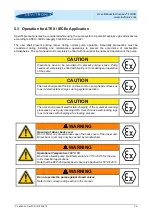
Page 36: ...ely be filled with liquid prior to enabling and operation of the pump CAUTION The user shall prevent friction on driver and on pump head surfaces as to avoid electrostatic charges during system operation CAUTION The user shall prevent electrostatic charging of the system at cleaning processes by using dry cleaning cloth User shall use wet cleaning rags to avoid issues with charging at a cleaning p...

Page 37: ... used On the labels of the packaging and on the biocompatibility declaration this serial number is the one on the lid see Figure 32 Figure 32 Serial number for traceability of pump head left on pump head right on label of package and the biocompatibility declaration 6 2 General Warnings and Cautions WARNING High Magnetic Field Strength of Impeller The pump head contains a rotor magnet with high fi...

Page 38: ...kwise as far as possible 6 4 3 Step 2 Axial Removal Smoothly remove the pump head axially 6 4 4 Step 3 Usage of Fixation Disc It is recommended to attach the Fixation Disc see Figure 33 to the pump head bottom in order to minimize magnetic leakage fields surrounding the impeller and hence reducing the tendency to attract other magnetic parts 6 5 Assembly into Hydraulic Circuit The following points...

Page 39: ... Levitronix Service Software can be used with a PC and a USB to RS485 interface cable 7 2 2 Troubleshooting with Levitronix Service Software The Levitronix Service Software allows communication with the pump system in connection with a PC and a USB interface The USB to RS485 adaptor cable as specified in Table 3 can be used to setup communication The software can be used for performing detailed tr...

Page 40: ...on protection by enclosure t IEC EN 80079 36 Explos Atmosph Non electr equipment for explosive atmosph Basic method and requirements IEC EN 80079 37 Explosive atmospheres Non electrical equipment for explosive atmospheres Non electrical type of protection constructional safety c control of ignition source b liquid immersion k The Levitronix Ex pump drivers are marked clearly and in accordance to t...

Page 41: ...if not avoided could result in property damage Signal word SEMI S1 0701 Safety alert for Warning and Caution Safety alert SEMI S1 0701 Safety alert for Danger Safety alert SEMI S1 0701 Caution refer to accompanying documents is used on article labels for reference to manual Refer to manual ISO 3864 Toxic material poison Hazard identification IEC 61310 Corrosive material corrosion Hazard identifica...

Reviews: