4.1 Electric cable selection
Lewmar recommends the installer
source and install cable that meets
the requirements of the standards and
regulations relevant to the installation
and codes of practice.
4.2 Receiver wiring diagram
WARNING! Connect only
to a DC power supply
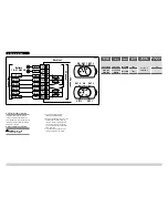
1. Figure 4.2-1 shows a typical
installation wiring diagram.
2. Receiver is supplied with 2 or 4 relay
outputs with one or two common
contacts. Common contact must be
connected to positive or negative
pole, according to the polarity of the
load connected.
• To avoid an overload due to short
circuit a 3A fuse must be fi tted.
4. Electrical Wiring
OUT 4 ON
OUT 2
ON OUT 1 OUT 2
OUT 3
OUT 1
1
2
3
4
5
6
7
8
OUT 1
OUT 2
OUT 3
OUT 4
OUT 1
+/–Vcom
OUT 2
OUT 3
OUT 4
A2
A1
C01
B2
B3
B1
B4
C02
Battery
10–31 Vdc 3 A
+/–Vcom
4 Channel
2 Channel
Connections
Receiver
4.2-1
Receiver /
Transmitter
Supply
Frequency
Protection
Rating
Operating
Temperature
Maximum Load
10 - 30 V DC
2 & 4 Channel
10 to 30 Vdc
433.92 MHz
IP65
0 to +70 °C
32 to 158 °F
3 A
68001005
68001006
2 x 1.5 V AAA
Alkaline
433.92 MHz
IP66
-


