background image

32

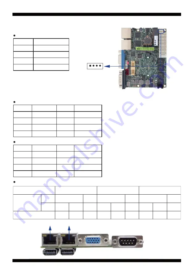
 CO1: I C Bus 4pin (1.25mm)Wafer

3-14 I C Bus Interface

2

PIN NO.

Description

1

+3.3V

2

GND

3

I C Clock

4

I C DATA

2

CO1

pin1

2

2

 CL1/CL2 : RJ45 LAN port Giga /100Mb( RJ45 Jack)

 CL11/CL21 : LAN port Giga /100Mb 2x5pin (2.0mm) wafer

 RJ45 LAN Connector--- LED de

fi

 ne Giga/100/10MB Connector

SPEED

Indicate

LAN Light

Back

Back

Back

Front

Front

Front

ACT

ACT

ACT

ACT

ACT

ACT

Orange Orange Green

Orange Orange

Orange Orange

Link

Link

Link

Red

Side

LED

10 Mbps

100Mbps

1000 Mbps

3-15 LAN Interface

PIN NO.

Description

PIN NO.

Description

1

TR0-/TX+

5

TR2-/NC

2

TR0+/TX-

6

TR2+/RX-

3

TR1-/RX+

7

TR3-/NC

4

TR1+/NC

8

TR3+/NC

PIN NO.

Description

PIN NO.

Description

1

TR0-/TX+

2

TR0+/TX-

3

TR2+/NC

4

TR1+/RX-

5

TR1-/RX+

6

TR2-/NC

7

TR3-/NC

8

TR3+/NC

CL2

CL1

Summary of Contents for 2I385A

Page 1: ...el Bay Trail I E3815 E3845 E3825 Single Core 1 46 GHz Quad Core 1 91 GHz Dual Core 1 33 GHz CPU Intel Bay Trail D J1900 Quad Core 2 0 GHz CPU 2 x Intel GbE LAN 2 x PCIe mini card slots VGA Audio SATA...

Page 2: ...MAP BOTTOM 2 5 DIAGRAM 2I385A 2 5 1 DIAGRAM 2I385CW 2 5 2 BOTTOM SIDE DIAGRAM 2I385A 2I385CW 2 6 LIST OF JUMPERS 2 7 JUMPER SETTING DESCRIPTION 2 8 JSB1 COMS DATA CLEAR 2 9 JVL1 LCD PANEL POWER SELEC...

Page 3: ...NFIGURATION 4 6 6 CONSOLE REDIRECTION 4 6 7 ACPI TABLE FEATURES CONTROL 4 7 SECURITY 4 8 POWER 4 9 BOOT 4 9 1 LEGACY 4 9 2 BOOT TYPE ORDER 4 10 EXIT 4 11 DEVICE MANAAGER 4 11 1 SIO FINTEK81801U 4 11 2...

Page 4: ...ON TEST APPENDIX B RESOLUTION LIST APPENDIX C F75111N I C DIO DEVICE 1 1 IO DEVICE F75111 UNDER DOS 1 2 IO DEVICE F75111 UNDER WINDOWS 1 3 IO DEVICE F75111 VB6 UNDER WINDOWS 1 4 IO DEVICE F75111 UNDER...

Page 5: ...eeps the rights in the subject to change the contents of this manual without prior notices in order to improve the function design performance quality and reliability The author assumes no responsibil...

Page 6: ...ase deal with heat dissipation properly when buying single MB set 9 Please avoid approaching the heat sink area to prevent users from being scalded with fanless products 12 It is important to install...

Page 7: ...U if you change modify any parts of the CPU cooler 6 Please wear wrist strap and attach it to a metal part of the system unit before handling a component You can also touch an object which is ground c...

Page 8: ...3 2 1 3 1 2 3 Photo 1 Insert Unplug...

Page 9: ...el and flexible expansion The 2I385A CW supports two LAN ports of 10 100 1G Ethernet for various and seamless broadband connectivity With Wake On LAN function and the PXE function in BIOS these are pe...

Page 10: ...l LAN ports 5 Support 4 x COM ports and 4 x USB 2 0 6 Support extended 2 x Mini PCIe card full size half size 7 Support one SATA connector with independent DMA operation supported 8 Hardware digital I...

Page 11: ...32 or 485 7 USB 4 x USB 2 0 2 external 2 internal 8 Sound ALC886 HD Audio Specification 1 0 Two channel sound chipset 9 Audio Amplifier TPA2011D1 Class D 2 5W 4 or 1 5W 8 chipset 2I385C 10 WDT DIO Har...

Page 12: ...lling the Mini PCI e Card 1 Unfasten the round headed M2 6 screw for half size Mini PCI e 3 Fasten a round headed M2 6 screw 2 Install a mSATA card at the angle of 45 The half size Mini PCI e slot sup...

Page 13: ...8 1 Unscrew the screw on the board 3 Gently push down the Mini Card and screw the screw back 2 Plug in the Mini Card in a 45 angle 1 4 Directions for installing the Mini Card...

Page 14: ...2 0 1 4 DC JK 1 5 6G5212 0301 0300 30W Power Adapter 12V 2 5A LF L Type EA10301 M06 EDAC 1 The packing list above is for the users who purchase single motherboard The users who purchase the board wit...

Page 15: ...strap before handling the 2I385A 2I385CW for harmlessly discharge any static electricity through the strap 2 Please use anti static pad to put any components parts or tools on the pad whenever you wor...

Page 16: ...here any visible damage on the board DO NOT CONTINUE TO INSTALL THIS BOARD CONTACT THE DEALER YOU PURCHASED THIS BOARD FROM IMMEDIATELY 4 Check your optional parts i e DDR CF etc all necessary jumpers...

Page 17: ...12 2 3 Dimension 2I385A 2I385CW...

Page 18: ...13 2 4 Layout 2I385A 2I385CW Connector and Jumper CALR1 CIO1 CO1 CFP1 CA3 CC2 CC3 CC4 CT1 CPP1 CPI1 CU3 JVL1 LVDS1 CU4 CPO1 CL2 CL1 CG1 CC1 JSB1 MPCE1 MPCE2...

Page 19: ...14 2 4 1 Layout 2I385A 2I385CW Connector and Jumper Bottom SATA1 CU2 CU1...

Page 20: ...DI 4DO Front Panel COM2 COM3 COM4 Touch SMBus COM1 USB2 0 USB2 0 12V 5V Out VGA DC IN 12V COMS ClearJumper RJ45 LAN 10M 100M 1000M Mini Card Socket 1 PCIe mSATA Auto detect USB SMBus Panel Power Selec...

Page 21: ...16 2 4 3 Layout 2I385A 2I385CW Function MAP Bottom SATA Genll USB2 0 USB2 0...

Page 22: ...17 2 5 Diagram 2I385A CALR1 CIO1 CFP1 CA3 CC2 CC3 CC4 CO1 CPI1 CPP1 CU3 JVL1 CU4 CPO1 CL2 CL1 CG1 CC1 JSB1 MPCE1 MPCE2 BAT1...

Page 23: ...18 2 5 1 Diagram 2I385CW CALR1 CIO1 CFP1 CA3 CC2 CC3 CC4 CT1 CO1 CPI1 CPP1 CU3 JVL1 LVDS1 CU4 CPO1 CL2 CL1 CG1 CC1 JSB1 MPCE1 MPCE2 BAT1...

Page 24: ...19 2 5 2 Bottom Side Diagram 2I385A 2I385CW SATA1 CU2 CU1 BACK Panel COM VGA USB USB LAN2 LAN1...

Page 25: ...circuit without the plastic cap Some jumpers have three pins labeled 1 2 and 3 You could connect either pin 1 and 2 or 2 and 3 The below figure 2 2 shows the examples of different jumper settings in t...

Page 26: ...tore the CMOS data To clear the CMOS follow the procedures below 1 Turn off the system and unplug teh AC power 2 Remove DC 12V power cable from DC 12V power connector 3 Locate JSB1 and close pin 1 2 f...

Page 27: ...22 2 9 JVL1 LCD panel power select Note Attention Check Device Power in spec JVL1 Description 1 2 5V 2 3 3 3V JVL1 5V 3 3V 1 1 2 2 3 3...

Page 28: ...afer CPI1 DC 12V IN 1x4 pin 2 0mm Red wafer connector CPP1 Panel inverter power connector 1x5 pin 2 0mm wafer CPO1 12V 5V power output 4 pin 2 0mm Black wafer connector CT1 Touch screen device 2x5 pin...

Page 29: ...in this board power RTC consumption 2 7uA 2 If adaptor always plug in RTC power consumption 0 1uA CPI1 DC in 1x4 2 0mm Wafer Internal connector Red PIN NO Description 1 GND 2 DC IN 3 DC IN 4 GND CPI1...

Page 30: ...oltage output PIN NO Description 1 5V 2 GND 3 GND 4 12V CPO1 pin1 3 5 Front Panel Pin Header CFP1 Front Panel connector 2x5pin 2 0mm wafer PIN NO Description PIN NO Description 1 Power button pin 2 Po...

Page 31: ...DATA1 28 Channel 1 DATA0 29 Channel 1 DATA1 30 Channel 1 DATA0 Note 1 LVDS interface support 18 24bits two channel 2 JVL1 LVDS panel 5V 3 3V default Voltage select 3 LVDS1 PIN 1 for panel backlight a...

Page 32: ...Sense 3 Top Sense 4 Top 5 Right 6 Right Sense 7 Left 8 Left Sense 9 GND 10 NC PIN NO Description PIN NO Description 1 Bottom 2 N A 3 N A 4 Top 5 Right 6 N A 7 Left 8 N A 9 GND 10 KEY PIN NO Descripti...

Page 33: ...pin 2 0mm Wafer CALR1 Amplifier Line out Right Left channel 4pin 1 25mm wafer PIN NO Description PIN NO Description 1 Line out R 2 MIC IN 3 Line in R 4 GND 5 GND 6 SPDIF OUT 7 Line in L 8 5V 9 Line ou...

Page 34: ...2 RS485 Data 7 NC 3 NC 8 NC 4 NC 9 NC 5 GND PIN NO Description PIN NO Description 1 RS422 TX 6 NC 2 RS422 TX 7 NC 3 RS422 RX 8 NC 4 RS422 RX 9 NC 5 GND Note 1 SATA1 support SATA 2 0 spec update 3Gb se...

Page 35: ...CD 2 RXD 3 TXD 4 DTR 5 GND 6 DSR 7 RTS 8 CTS 9 RI 10 5V Note 1 CC2 CC3 connector default RS232 function OEM RS485 2 CC4 connector default RS485 function OEM RS232 3 BIOS need setting to RS485 mode CG1...

Page 36: ...unter to zero The reset timer have 10 20 tolerance upon the Temperature Note If want to SDK support Please contact to sales window Please refer to page 82 for APPENDIX C F75111N I C DIO DECICE 2 CIO1...

Page 37: ...ga 100 10MB Connector SPEED Indicate LAN Light Back Back Back Front Front Front ACT ACT ACT ACT ACT ACT Orange Orange Green Orange Orange Orange Orange Link Link Link Red Side LED 10 Mbps 100Mbps 1000...

Page 38: ...3 CU1 CU2 USB2 0 Port Type A CU3 CU4 USB2 0 Port 1x4pin 1 25mm Wafer 3 16 USB Interface PIN NO Description 1 5V 2 DATA 3 DATA 4 GND PIN NO Description 1 5V 2 DATA 3 DATA 4 GND CU3 CU4 pin1 pin1 CU2 CU...

Page 39: ...nterface PIN NO Description 1 GND 2 TX 3 TX 4 GND 5 RX 6 RX 7 GND Note 1 SATA1 support SATA 2 0 spec update 3Gb sec 2 CPO1 provide SATA HDD power 12V GND 5V 3 The SATA signal share with mSATA of MPCE1...

Page 40: ...EY KEY 17 NC 18 GND 19 NC 20 NC 21 GND 22 Reset 23 PCIe RX mSATA RX 24 3 3V 25 PCIe RX mSATA RX 26 GND 27 GND 28 1 5V 29 GND 30 SMB CLK 31 PCIe TX mSATA TX 32 SMB DATA 33 PCIe TX mSATA TX 34 GND 35 GN...

Page 41: ...VS CFP1 2x5 10Pin 2 0mm JST B10B PHDSS PHDR 10VS CIO1 2x5 10Pin 2 0mm JST B10B PHDSS PHDR 10VS CL11 2x4 8Pin 2 0mm JST B8B PHDSS PHDR 08VS CL21 2x4 8Pin 2 0mm JST B8B PHDSS PHDR 08VS CO1 1x4 4Pin 1 25...

Page 42: ...actor of system stability and of ensuring your system performance at best In the BIOS Setup main menu you can see several options We will explain these options in the following pages First let us see...

Page 43: ...f the function keys you may use here Press left right to select screen Press up down to choose in the main menu the option you want to confirm or to modify Press Enter to select Press keys when you wa...

Page 44: ...pop up a help window that describes the appropriate keys to use and the possible selections for the highlighted item To exit the Help Window press Esc 4 3 Getting Help Status Page Setup Menu Option P...

Page 45: ...ress the right or left arrow key on the keyboard to switch from menu bar The selected one is highlighted 4 4 Menu Bars 4 5 Main There are six menu bars on top of BIOS screen Main menu screen includes...

Page 46: ...se refer section 4 6 3 Please refer section 4 6 5 Set the Time Please use Tab to switch between data elements PCI Express Configuration Thermal Configuration Boot Configuration Video Configuration SAT...

Page 47: ...Please refer section 4 6 7 ACPI Table Features Control 4 6 1 Boot Configuration Select Power on state for Numlock default is ON Numlock 4 6 2 PCI Express Configuration PCIe 1 2 3 4 configuration setti...

Page 48: ...4 The optional settings are Enabled default Disabled The optional settings are Gen1 default Gen2 The optional settings are Disabled default Enabled Control the PCI Express Root Port Select PCI Express...

Page 49: ...8bit default 800 x 480 18bit 1024 x 600 18bit 1280 x 800 18bit 1366 x 768 18bit 800 x 600 24bit 1024 x 768 24bit 1280 x 800 24bit 1366 x 768 24bit 1280 x 1024 48bit 1440 x 900 48bit 1600 x 1200 48bit...

Page 50: ...assive Trip point The default of the passive trip point is 105 Use this item to select DVMT 5 0 total graphics memory size used by the internal graphics device The optional settings are 128M 256M defa...

Page 51: ...ates the maximum speed the SATA controller can support The optional settings Gen1 Gen2 default Legacy IDE or Native IDE MODE The optional settings Legacy IDE or Native IDE default Use this item to Ena...

Page 52: ...Console Redirection The optional settings are Enabled Disabled default The optional settings are 115200 default 57600 38400 19200 9600 4800 2400 1200 The optional settings are 8 Bits default 7 Bits Th...

Page 53: ...default RTS CTS XON XOFF Stop Bits Flow Control 4 6 7 ACPI Table Features Control 4 7 Security Select ACPI sleep state the system will enter when the SUSPEND button is pressed The optional settings DS...

Page 54: ...cters 3 Hit Enter key to submit Supervisor Password 4 8 Power Determines the action taken when the system power is off and the PCI power management Enable wake up event occurs The optional settings En...

Page 55: ...EFI boot type default is Dual boot type The optional settings are Enabled default Disabled Determine EFI device first or legacy device first The optional settings EFI device first Legacy device first...

Page 56: ...51 Select Normal Boot option priority or Advance Boot option priority The optional settings Normal default Advance Normal Boot Menu 4 9 1 Legacy...

Page 57: ...52 4 9 2 Boot Type Order Setting the boot type priority The default settings is 1 USB drive 2 Hard Disk Drive 3 CD DVD ROM drive 4 Others Boot Type Order...

Page 58: ...changes but doesn t restart This item allows user restart the system but no saving the changes Use this item to restore the optimal default for all the setup options Use this item to cancel all the s...

Page 59: ...Device Manager Please refer section 4 11 1 Please press the key F10 when boot up to go into the Device Manager menu Serial Port 1 2 Configuration Please refer section 4 11 2 Serial Port 3 4 5 6 Config...

Page 60: ...device The optional settings are IO 3F8h IRQ 4 default IO 3E8h IRQ 3 4 IO 2E8h IRQ 3 4 IO 2F8h IRQ 3 4 Use this item to enable or disable serial port COM1 or COM2 The optional settings are Enabled de...

Page 61: ...hardware select to RS485 mode please enter to RS485 driver It is the auto flow function for RS485 Serial Port 2 Base IO Address Interrupt Serial Mode Serial Mode Power Failure This item specifies whe...

Page 62: ...57 4 11 2 Hardware Monitor Press Enter to view PC health status This section shows the status of your CPU Fan and overall system This is only available when there is Hardware Monitor function onboard...

Page 63: ...10 default IO 2F8h IRQ 3 4 5 6 7 10 11 IO 2E8h IRQ 3 4 5 6 7 10 11 IO 3F8h IRQ 3 4 5 6 7 10 11 IO 4F8h IRQ 3 4 5 6 7 10 11 IO 4E8h IRQ 3 4 5 6 7 10 11 Use this item to enable or disable serial port C...

Page 64: ...hardware select to RS232 or RS422 mode COM1 to COM3 default RS232 please enter to RS232 driver RS485 driver When hardware select to RS485 mode please enter to RS485 driver It is the auto flow function...

Page 65: ...detect software SYSTEM INSTALL 1 Auto Detect Main board and OS to AUTOMATIC DRIVER INSTALLATION menu 2 Browse DVD to view the contents of the DVD 3 Exit to exit SYSTEM INSTALL menu DRIVER INSTALLATIO...

Page 66: ...61 AUTOMATIC DRIVER INSTALLATION menu...

Page 67: ...ver FOR Win 7 only 4 xHCI Install Intel USB 3 0 xHCI driver FOR Win 7 only 5 HD Audio Install HD Audio Codec driver 6 MBI Install MBI driver FOR Win 8 8 1 only 7 LAN To the LAN driver Readme file 8 TX...

Page 68: ...Driver example for WIN8 64bit 1 At the AUTOMATIC DRIVER INSTALLATION menu screen click INF 2 At the Intel Chipset Device Software screen click Next 3 At the License Agreement screen click Yes 4 At the...

Page 69: ...ck Finish restart computer NOTE SYSTEM INSTALL will auto detect file path For Windows 7 64 32 bit X driver INTEL BAY INF WIN7 infinst_autol exe For Windows 8 8 1 32 64 bit X driver INTEL BAY INF WIN_8...

Page 70: ...iver example for WIN8 64bit 1 At the AUTOMATIC DRIVER INSTALLATION menu screen click VGA 3 At the License Agreement screen Click Yes 2 At the Welcome to the Setup Program screen Click Next 4 At the Re...

Page 71: ...ill auto detect file path For Windows 7 32 bit X driver INTEL BAY VGA WIN_7_32 Setup exe For Windows 7 64 bit X driver INTEL BAY VGA WIN_7_64 Setup exe For Windows 8 Windows 8 1 32 bit X driver INTEL...

Page 72: ...Driver FOR Windows 7 only 1 At the AUTOMATIC DRIVER INSTALLATION menu screen click Serial IO 3 At the License Agreement screen Click Yes 4 At the Setup type screen select complete and Click Next 2 At...

Page 73: ...gram screen Click Install 6 Click Finish and restart computer NOTE SYSTEM INSTALL will auto detect file path For Windows 7 32 bit X driver INTEL BAY SERIALIO WIN7_32Bit msi For Windows 7 64 bit X driv...

Page 74: ...Windows 7 only 1 At the AUTOMATIC DRIVER INSTALLATION menu screen Click USB 3 0 3 At the License Agreement screen Click Yes 2 At the Intel USB 3 0 extensible Host Controller Driver screen Click Next 4...

Page 75: ...0 5 At the Setup Progress screen Click Next 6 Click Finish to restart computer NOTE SYSTEM INSTALL will auto detect file path For Windows 7 32 64 bit X driver INTEL BAY XHCI Driver_Installer Setup exe...

Page 76: ...WIN8 64bit 1 At the AUTOMATIC DRIVER INSTALLATION menu click HD Audio 3 Click Finish to restart computer 2 Click Next NOTE SYSTEM INSTALL will auto detect file path For Windows 7 32 64 bit Windows 8...

Page 77: ...Driver FOR Win 8 8 1 only 1 At the AUTOMATIC DRIVER INSTALLATION menu click HD Audio 3 At the License Agreement screen Click Yes 2 At the Welcome to the Setup Program screen Click Next 4 At the Setup...

Page 78: ...73 5 Click Finish to restart computer NOTE SYSTEM INSTALL will auto detect file path For Windows 8 8 1 32 64 bit X driver INTEL BAY MBI Setup exe...

Page 79: ...TXE Install Intel TXE driver 5 7 1 TXE Install for WIN8 WIN8 1 1 At the AUTOMATIC DRIVER INSTALLATION menu click TXE 3 At the License Agreement screen Click Yes 2 At the Setup screen Click Next 4 Clic...

Page 80: ...k Finish restart computer NOTE SYSTEM INSTALL will auto detect file path For Windows 8 32 64 bit X driver INTEL BAY TXE WIN_8 SetupTXE exe For Windows 8 1 32 64 bit X driver INTEL BAY TXE WIN_8 1 Setu...

Page 81: ...WIN7 1 At the AUTOMATIC DRIVER INSTALLATION menu click TXE Patch Please install PXE Patch first 3 Click Finish restart computer 2 At the Windows Update screen Click Yes 4 At the AUTOMATIC DRIVER INST...

Page 82: ...XE WIN_7 kmdf 1 11 Win 6 1 x86 msu X driver INTEL BAY TXE WIN_7 kmdf 1 11 Win 6 1 x64 msu TXE X driver INTEL BAY TXE WIN_7 SetupTXE exe X driver INTEL BAY TXE WIN_7 SetupTXE exe 5 At the TXE Setup scr...

Page 83: ...ase enter your motherboard s name Insert your bootable disc into X X could be C A or others It depends on which type of storage device you use Start the computer and type X H2OFFT D EXE 2I385ACA2 ROM...

Page 84: ...49A 0 76A 0 58A 12V 0 14A 0 91A 0 67A 0 99A 0 78A 12V 0 09A 0 47A 0 33A 0 52A 0 40A 24V 12V 24V 0 14A 0 78A 0 61A 0 84A 0 66A 0 09A 0 42A 0 31A 0 46A 0 35A Operation Maximum Shut down Maximum In Put...

Page 85: ...he power consumption depends on your device choice Start up Power off 0 10A 0 96A 0 66A 1 13A 0 80A 12V 0 09A 0 81A 0 55A 1 06A 0 72A 12V 0 14A 1 06A 0 68A 1 22A 0 90A 12V 0 09A 0 57A 0 35A 0 63A 0 47...

Page 86: ...bit 32bit 1280 x 720 x 256 16bit 32bit 1280 x 768 x 256 16bit 32bit 1280 x 800 x 256 16bit 32bit 1280 x 960 x 256 16bit 32bit 1280 x 1024 x 256 16bit 32bit 1400 x 1050 x 256 16bit 32bit 1440 x 900 x 2...

Page 87: ...countdown and Reset Computer WriteI2CByte I2CADDR CONFIG 0x03 Set Watch Dog Timer function WriteI2CByte I2CADDR WDT_TIMER timer Set Watch Dog Timer range from 0 255 WriteI2CByte I2CADDR WDT_TIMER_CTL...

Page 88: ...able button to test WDT function 3 Press the Disable button to disable WDT 4 Check the Enable Loop box and press Enable to do WDT loop test 5 Press Install WDT to set the system to autorun this applic...

Page 89: ...ROL 0x00 This is setting low pulse output this Write_Byte F75111_INTERNAL_ADDR GPIO3X_PULSE_WIDTH_CONTROL 0x01 This selects the pulse width to 1mS this Write_Byte F75111_INTERNAL_ADDR GPIO3X_CONTROL_M...

Page 90: ...GPIO1X_INPUT_DATA byteGPIO1X Get value from GPIO1X this Read_Byte F75111_INTERNAL_ADDR GPIO3X_INPUT_DATA byteGPIO3X Get value from GPIO3X byteGPIO1X byteGPIO1X 0xF0 Mask unuseful value byteGPIO3X byte...

Page 91: ...rd info lexwiki index php IO_Device F75111_VB6 1 3 IO Device F75111 VB6 under Windows A Function Enable WDT timer Key in the value by seconds then system will reboot after value which you key in in le...

Page 92: ...Call WriteI2CByte H36 H0 End Function Function SetDOValue dovalue As Integer Call WriteI2CByte H23 H0 Call WriteI2CByte H20 HFF Call WriteI2CByte H2B HFF Call WriteI2CByte H21 dovalue End Function Fun...

Page 93: ...load and install the Code Block with command apt get install codeblocks Open an exist project F75111 cbp in Code Blocks click the compile button add an option pkg config libs gtk 2 0 gthread 2 0 in Pr...

Page 94: ...if there s disable signal received resent Enable WDT signal for a loop to prevent from reboot p s IO function In file SMBus c Initial internal F75111 Introduction void SMBusIoWrite BYTE byteOffset BY...

Page 95: ...output pin BYTE F75111 InterDigitalInput BYTE byteGPIO1X 0 BYTE byteGPIO3X 0 BYTE byteData 0 this Read_Byte F75111_INTERNAL_ADDR GPIO1X_INPUT_DATA byteGPIO1X Get value from GPIO1X this Read_Byte F7511...

Page 96: ...DDR WDT_TIMER_RANGE byteTimer set WatchDog range and timer WriteByte F75111_INTERNAL_ADDR WDT_CONFIGURATION WDT_TIMEOUT_FLAG WDT_ENABLE WDT_PULSE WDT_PSWIDTH_100MS Enable WatchDog Setting WatchDog con...

Reviews: