background image

PowerGATE™ Emergency Lighting Transfer Switch

Contact Lex Products:    

800.643.4460   info@lexproducts.com

4

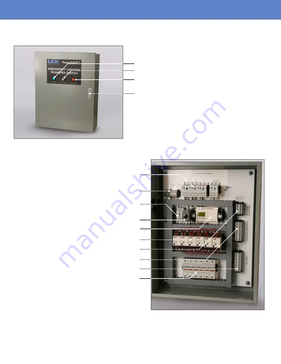
Lex PowerGATE

 Emergency Lighting Transfer Switch Components

Normal Operation Indicator

Transfer Relays

Test Key Switch
Emergency Operation Indicator

Door Latch and Lock

Emergency 3Ø Supply  

(Main version only)

Monitored Normal 3Ø Supply

Controller Supply Fuses

Voltage Dropout Adjustment

Programmable Logic Controller

Auxiliary, Fire Alarm & Generator Start

Circuits from Dimmers

To Load Circuits

20A Type J Fuses

Summary of Contents for PowerGATE LELTS-1 Series

Page 1: ...Emergency Lighting Transfer Switch Installation Instructions User Manual LM ELTS REV 000 Switches Panels PowerGATE ...

Page 2: ...0 info lexproducts com 2 Table of Contents 3 Introduction 4 Product Components 5 Step 1 Shipment Unpacking and Inspection 6 Step 2 Installation of the ELTS Enclosure 7 Step 3 Planning Wire Entry into the Cabinet 8 Step 4 Connecting Power 10 Step 5 Operation 11 Technical Support ...

Page 3: ...feed For the remainder of the document the different variants will be referred to as discrete feed and main feed WARNING This equipment has the potential to be the source of an electric shock hazard Take extreme caution when the cabinet door is opened and the system is energized This equipment should only be installed commissioned and serviced by qualified service personnel Tools Needed Blade scre...

Page 4: ...ponents Normal Operation Indicator Transfer Relays Test Key Switch Emergency Operation Indicator Door Latch and Lock Emergency 3Ø Supply Main version only Monitored Normal 3Ø Supply Controller Supply Fuses Voltage Dropout Adjustment Programmable Logic Controller Auxiliary Fire Alarm Generator Start Circuits from Dimmers To Load Circuits 20A Type J Fuses ...

Page 5: ...ess Crushed or punctured container 2 If you find damage document it to help with a claim against the shipper 3 Unpack your order and check the contents against the packing list to ensure your order is complete 4 Open the cabinet door and check for loose components or broken components as the result of shipping vibrations and handling Tighten anything that has come loose If it can t be tightened or...

Page 6: ...pace to meet NEC bend radius requirements Mount the cabinet on a load bearing wall in a location where it will not be subject to tampering or vandalism Choose a location where it will be the most likely to be secure from damage from fire flood or other conditions and incidents that will require its used If there are any doubts about about a location s suitability contact Lex Technical Services Do ...

Page 7: ...ectrical connections terminate in the top and right side of the cabinet Main Feed Series Panels The emergency power conduit enters the top of the panel directly above the lugs marked 208 VAC Emergency Power Discrete Feed Series Panels The emergency feed conduit circuits the normal feed circuits and the load circuits enter the right side of the panel close to their respective terminal blocks Contro...

Page 8: ...iscrete Feed On the Discrete Feed series panels connect each emergency supply circuit to the terminal block marked 120V Emergency Power Inputs located on the right side of the cabinet Tighten each connection to 25 lb in Connecting Normal Power Main Feed and Discrete Feed Versions The normal 120V circuits often from dimmers are connected to the terminal block marked as 120V Normal Power Inputs loca...

Page 9: ...the same normal feed as the circuits being transferred Connect the sensing wires from the normal feed to the three phases and neutral on the terminal block labelled 208 VAC Monitored Power Terminals accept 22 10 AWG conductors and should be tightened to 25 lb in NOTE Power sensing conductors must be 12 AWG or larger Connecting the Fire Alarm Interface You can connect your system to a fire alarm in...

Page 10: ... Switch Monitoring Inputs on the LCD 3 At this time the green indicator light in the cabinet door will be illuminated If this is not the case then the PLC will need to be placed in the active monitoring mode To place the PLC in monitoring mode 1 Press the Menu button 2 Press the down arrow button and select RUN 3 Once in the run mode the LCD will display Auto Switch Monitoring Inputs and the green...

Page 11: ...tem is switching from the emergency mode back to the normal mode there is a 1 minute delay from the time the normal monitored inputs are recognized until the time the circuit transfer contactor are switched and the system is energized with normal power Technical Services Team Lex Products is available to help answer any installation or operation inquiries If you have questions need technical advic...

Page 12: ...ucts com 800 643 4460 Copyright Lex Products 2021 Produced in the United States of America 05 30 All Rights Reserved Lex Products logo and lexproducts com are trademarks or registered trademarks of Lex Products in the United States other countries or both PowerGATE Emergency Lighting Transfer Switch Installation Instructions User Manual Switches Panels PowerGATE TYPE 3R WE DELIVER THE POWERTM ...

Reviews: