3-20
Service Manual
4036-402
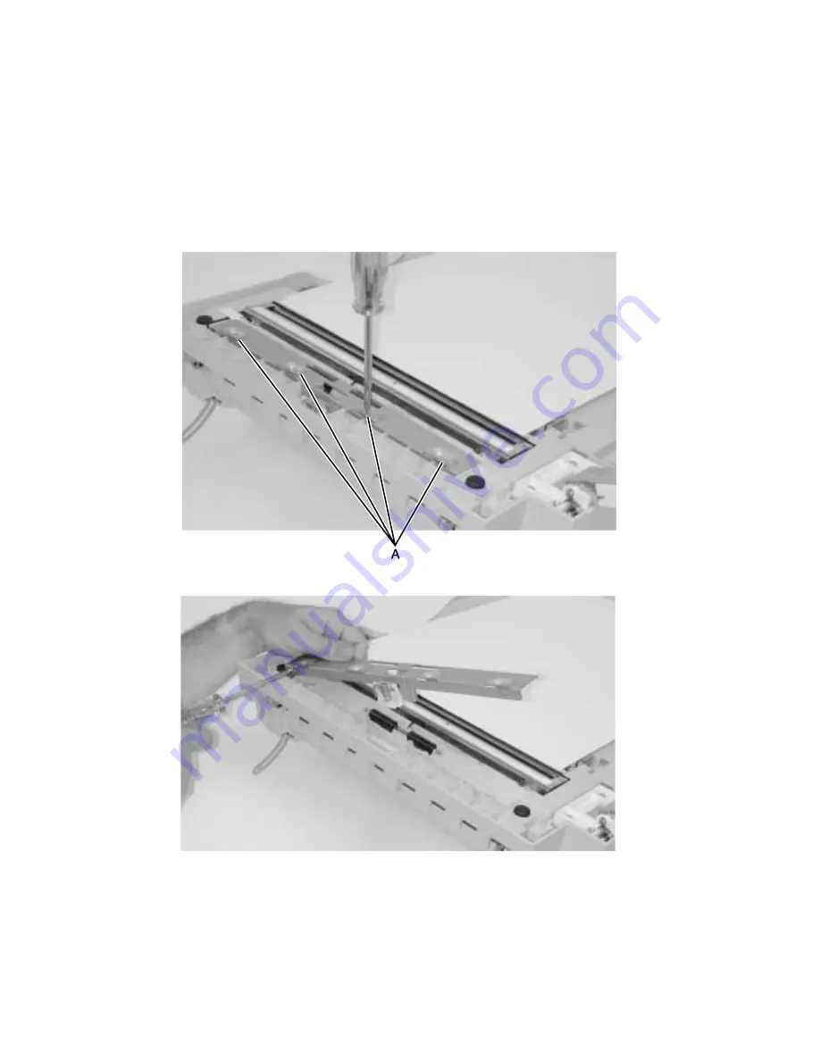
Internal ADF CCD subassembly
Warning: Screws for the CCD card in the optical unit are as shown in
“Charge-coupled device
(CCD) card screws” on page 3-5
. These screws have a red coating indicating they
should never be loosened.
1.
Remove the ADF drive motor. See
“ADF drive motor” on page 3-13
.
2.
Turn the ADF unit upside down.
3.
Remove the four screws from the lower ADF frame plate.
4.
Remove the ground screw.
5.
Remove the idler rollers.
Summary of Contents for 16C0365 - 5500 MFP
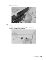
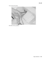
Page 49: ...Repair information 3 25 4036 402 3 Remove the pick pad ...
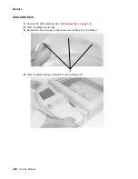
Page 55: ...Repair information 3 31 4036 402 5 Disconnect the cables 6 Remove the user interface ...
Page 68: ...3 44 Service Manual 4036 402 ...
Page 69: ...Connector locations 4 1 4036 402 4 Connector locations Locations Paper path and sensors ...
Page 70: ...4 2 Service Manual 4036 402 Internal view ...
Page 76: ...5 4 Service Manual 4036 402 ...
Page 78: ...6 2 Service Manual 4036 402 Assembly 1 Upper Scanner ...
Page 86: ...I 4 Service Manual 4036 402 ...


