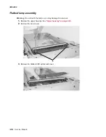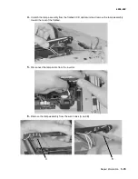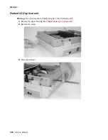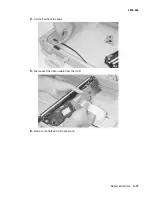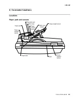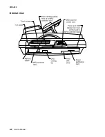
Connector locations
4-3
4036-402
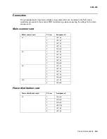
Connectors
The pin assignments shown are voltages and grounds which can be tested in the field. Use a
multimeter grounded to the scanner MFD controller cage when measuring the voltage for the main
scanner card.
Main scanner card
Power distribution card
Main scanner card
Pin no.
Assignment
J3
1
+5V dc
2
+5V dc
3
+5V dc
4
+5V dc
5
Ground
J6
1
+5V dc
2
+5V dc
3
+5V dc
4
+5V dc
5
Ground
J9
1
+5V dc
2
+5V dc
3
+5V dc
5
+5V dc
5
Ground
J10
1
+5V dc
2
Ground
Power distribution card
Pin no.
Assignment
J2
1
Ground
2
Ground
3
Ground
4
+24V dc
5
+5V dc
6
+5V dc
Summary of Contents for 16C0365 - 5500 MFP
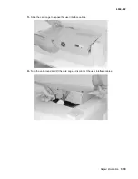
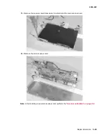
Page 49: ...Repair information 3 25 4036 402 3 Remove the pick pad ...
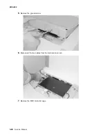
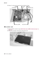
Page 55: ...Repair information 3 31 4036 402 5 Disconnect the cables 6 Remove the user interface ...
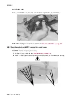
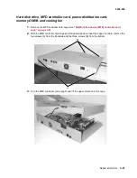
Page 68: ...3 44 Service Manual 4036 402 ...
Page 69: ...Connector locations 4 1 4036 402 4 Connector locations Locations Paper path and sensors ...
Page 70: ...4 2 Service Manual 4036 402 Internal view ...
Page 76: ...5 4 Service Manual 4036 402 ...
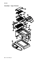
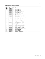
Page 78: ...6 2 Service Manual 4036 402 Assembly 1 Upper Scanner ...
Page 86: ...I 4 Service Manual 4036 402 ...


