background image

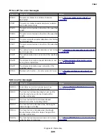
Error code Description

Action

929.01

The sensor (toner empty) does not provide toner
level feedback or the print cartridge is damaged.

Go to 

“Sensor (toner empty) service check” on

page 249

.

929.02

929.03

930.00

Possible causes:

A non

supported printhead is installed.

Hsync signal is intermittent or noisy.

Printhead ID resistor circuit is not to spec.

Replace the printhead.

Go to 

“Printhead assembly removal” on

page 377

.

931.00

The hsync signal is missing or not at the correct
voltage.

Go to 

“Printhead failure service check” on

page 250

.

932.00

The hsync signal is missing or not at the correct
voltage.

Replace the printhead.

Go to 

“Printhead assembly removal” on

page 377

.

933.00

934.00

The signals driving the polygon motor may have
been corrupted, or the cable may be loose, or the
motor may be bad.

Go to 

“Motor (printhead polygon mirror) service

check” on page 251

.

935.00

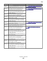
936.xx–945.xx error messages

Error code Description

Action

936.10

The main drive motor assembly may be faulty or has
failed.

Go to 

“Main drive motor assembly service

check” on page 251

.

936.11

936.20

936.21

936.30

936.31

The main drive motor assembly may be faulty or has
failed.

Go to 

“Main drive motor assembly service

check” on page 251

.

936.60

936.61

936.90

936.91

937.40

The main drive motor assembly may be faulty or has
failed.

Go to 

“Main drive motor assembly service

check” on page 251

.

937.41

937.50

937.51

937.70

7462

Diagnostic information

228

Summary of Contents for 7462 series

Page 1: ...X65x Series Machine Type 7462 xxxx Service Manual Start diagnostics Maintenance Safety and notices Trademarks Index June 28 2016 www lexmark com P N 12G9823 ...

Page 2: ... Any reference to a product program or service is not intended to state or imply that only that product program or service may be used Any functionally equivalent product program or service that does not infringe any existing intellectual property right may be used instead Evaluation and verification of operation in conjunction with other products programs or services except those expressly designa...

Page 3: ...overview 39 Performing the initial troubleshooting check 39 Power on Reset POR sequence 40 Using Safe Mode 40 Fixing print quality issues 41 Initial print quality check 42 Faint print low contrast check 42 Repeating defects check 44 Blank pages check 44 Solid black pages check 46 Vertical lines and bands process direction check 48 Horizontal white stripes and bands side to side direction check 49 ...

Page 4: ...t cartridge 185 Close finisher side door 185 Connect x bps 185 Dialing 185 Disk corrupted 185 Disk Full Scan Job Canceled 185 Fax failed 186 Fax memory full 186 Fax partition inoperative Contact system administrator 186 Fax server To Format not set up Contact system administrator 186 Fax Station Name not set up 186 Fax Station Number not set up 186 Flushing buffer 186 Insert staple cartridge 187 In...

Page 5: ... disk space 192 Sending page n 192 Serial x 192 Set clock 193 SMTP server not set up Contact system administrator 193 Some held jobs were not restored 193 System busy preparing resources for job 193 System busy preparing resources for job Deleting held job s 193 Unsupported disk 193 Unsupported USB device please remove 193 Unsupported USB hub please remove 193 USB USB x 193 Waiting for redial 193 ...

Page 6: ... disks installed 198 58 Too many flash options installed 198 58 Too many trays attached 199 59 Incompatible envelope feeder 199 59 Incompatible output bin x 199 59 Incompatible tray x 199 61 Remove defective disk 199 62 Disk full 199 63 Unformatted disk 200 80 Routine maintenance needed 200 81 Routine Maintenance 200 88 Cartridge low 200 88 yy Cartridge nearly low 200 88 yy Replace cartridge 200 20...

Page 7: ...212 Too Many Trays Attached service check 212 Incompatible Duplex service check 212 Incompatible Envelope Feeder service check 212 Incompatible Output Bin x service check 213 Incompatible Output Tray x service check 213 Defective Disk service check 213 Disk Full service check 213 Routine Maintenance Needed service check 214 Replace fuser service check 214 Replace cartridge service check 214 Printe...

Page 8: ...Menus 281 PPDS Emulation 281 Factory Defaults 281 Energy Conserve 282 Min Copy Memory 282 NumPad Job Assist 282 Format Fax Storage 282 Fax Storage Location 282 ADF Edge Erase 283 FB Edge Erase 283 Scanner Manual Registration 283 Disable Scanner 284 Paper Prompts 284 Envelope Prompts 284 Action for Prompts 285 Jobs on Disk 285 Disk Encryption 285 Wipe Disk 286 Font Sharpening 286 Require Standby 28...

Page 9: ... 309 Main cooling fan removal 311 Main drive motor assembly removal 312 MPF pick solenoid assembly removal 313 Print cartridge clamp assembly removal 316 Print cartridge ID connector assembly removal 316 Left side cover removal models X651 X652 X654 and X656 317 Left side cover removal model X658 318 Switch media size assembly removal 320 System card assembly removal 321 Right side removals 323 Du...

Page 10: ...val 353 Transfer deflector removal 353 Print cartridge cover assembly removal model X658 355 Bottom side removals 355 Duplex assembly removal 355 Duplex input sensor assembly removal 356 Front duplex guide assembly removal 357 Media out actuator removal 358 Option drive shaft removal 358 Pick arm assembly removal 359 Pick roll assembly removal 362 Sensor media level removal 363 Sensor media out rem...

Page 11: ...p cover removal 391 4 bin mailbox assembly deflector gate solenoid removal 393 4 bin mailbox assembly transport solenoid removal 393 4 bin mailbox assembly spring removal 394 4 bin mailbox assembly deflector gate bin 1 through 3 removal 395 4 bin mailbox assembly deflector gate bin 4 removal 396 4 bin mailbox assembly sensor pass through removal 397 4 bin mailbox assembly sensor mailbox empty removal...

Page 12: ...removal 436 High capacity stacker media output bin assembly removal 436 High capacity stacker controller card cover panel removal 437 High capacity stacker switch media bin HP removal 438 High capacity stacker sensor media bin full assembly removal 438 High capacity stacker sensor media bin full bracket assembly removal 439 High capacity stacker controller card assembly upper and lower removal 440...

Page 13: ...er interface cable assembly removal 472 Output expander removals 473 Output expander rear door assembly removal 473 Output expander left outer cover removal 474 Output expander left inner cover removal 474 Output expander right outer cover removal 475 Output expander right inner cover removal 475 Output expander media bin latch left and right removal 476 Output expander media output bin assembly r...

Page 14: ... cable assembly removal 507 Scanner interface card assembly removal 508 Scanner cooling fan filter removal 508 Scanner cooling fan removal 509 Scanner support right rear cover removal model X658 510 Scanner support right inner cover removal model X658 511 Scanner support right cover removal model X658 512 Scanner support left rear cover removal model X658 513 Scanner support left front cover remova...

Page 15: ...al 547 Sensor ADF media exit fan bracket assembly removal models X654 X656 and X658 548 Sensor ADF media exit bracket assembly removal model X651 549 ADF transport drive motor bracket assembly with cable removal 550 ADF feed drive motor assembly removal 551 ADF pick roll position cam assembly removal 552 ADF solenoid assembly removal 554 Sensor ADF top door interlock removal 554 Sensor ADF lower d...

Page 16: ...ser and LVPS card assemblies 591 Assembly 10 Flatbed scanner 593 Assembly 11 ADF unit assembly 595 Assembly 12 ADF covers 597 Assembly 13 ADF feed and drive 599 Assembly 14 ADF electronics 602 Assembly 15 250 Sheet option tray assembly X651 X652 X654 and X656 605 Assembly 16 550 Sheet option tray assembly X651 X652 X654 and X656 608 Assembly 17 550 Sheet option tray assembly X658 611 Assembly 18 H...

Page 17: ...options 647 Media handling options 647 Appendix C Theory of operation 649 POR sequence 649 Printer control 649 Printer theory 650 Models X651 X652 X654 and X656 paper path rolls and sensors 650 Model X658 paper path rolls and sensors 651 Functions of main components 651 Media tray assembly 653 MPF 655 Registration 656 Transfer 657 Polygon printhead assembly 657 Fuser 659 Fuser components 660 Fuser...

Page 18: ...y assembly 673 250 sheet 550 sheet tray assembly 674 Paper path rolls and sensors 677 Media tray assembly 680 Duplex 682 Appendix D Acronyms 685 Acronyms 685 Index 687 Part number index 699 Part name index 713 7462 Table of contents 18 ...

Page 19: ...ind die die Werte für Klasse I überschreitet Avis relatif à l utilisation du laser L imprimante est certifiée conforme aux exigences de la réglementation des Etats Unis relative aux produits laser DHHS 21 CFR Chapter I Subchapter J for Class I 1 Pour les autres pays elle est certifiée conforme aux exigences des normes IEC 60825 1 relatives aux produits laser de classe I Les produits laser de Classe ...

Page 20: ...tas Laserinformatie Deze printer is in de Verenigde Staten gecertificeerd als een product dat voldoet aan de vereisten van DHHS 21 CFR hoofdstuk 1 paragraaf J voor laserproducten van klasse I 1 Elders is de printer gecertificeerd als een laserproduct van klasse I dat voldoet aan de vereisten van IEC 60825 1 Laserproducten van klasse I worden geacht geen gevaar op te leveren De printer bevat intern e...

Page 21: ...m opererer i bølgelengder på 770 795 nanometer Lasersystemet og skriveren er utformet slik at mennesker ikke utsettes for laserstråling utover nivået i klasse I under normal drift vedlikehold eller foreskrevet service Avís sobre el làser Als EUA la impressora està certificada de conformitat amb els requisits del capítol I apartat J del CFR 21 del Departament de Salut i Serveis Humans per a producte...

Page 22: ...n for this product has been prepared for use by a professional service person and is not intended to be used by others There may be an increased risk of electric shock and personal injury during disassembly and servicing of this product Professional service personnel should understand this and take necessary precautions CAUTION POTENTIAL INJURY The lithium battery in this product is not intended t...

Page 23: ...auf Tests und Zulassungen des ursprünglichen Modells und bestimmter Bauteile Bei Verwendung nicht genehmigter Ersatzteile wird vom Hersteller keine Verantwortung oder Haftung für die Sicherheit übernommen Die Wartungsinformationen für dieses Produkt sind ausschließlich für die Verwendung durch einen Wartungsfachmann bestimmt Während des Auseinandernehmens und der Wartung des Geräts besteht ein zus...

Page 24: ...nte e regulamentos locais Informació de Seguretat La seguretat d aquest producte es basa en l avaluació i aprovació del disseny original i els components específics El fabricant no es fa responsable de les qüestions de seguretat si s utilitzen peces de recanvi no autoritzades La informació pel manteniment d aquest producte està orientada exclusivament a professionals i no està destinada a ningú que...

Page 25: ...万一使用来经许可的替换部件 制造商 不对安全性负责 本产品的维护信息仅供专业服务人员使用 并不打算证其他人使用 本产品在拆卸 维修时 遭受电击或人员受伤的危险性会增高 专业服务人员对这点必须有所了触 并采 取必要的预防措施 当心一可能的伤害 本产品中的锂电池不可更换 如果不正确更换锂电池 可能会有爆炸危险 不要再 充电 拆解或 焚烧锂电池 丢弃旧的锂电池时应按照制造商的指导及当地法规进行处理 7462 Notices and safety information 25 ...

Page 26: ...7462 26 ...

Page 27: ...tains the available options and other features of the product Appendix C Theory of operation contains the theory of operation Appendix D Acronyms contains the list of acronyms in the manual and their meanings Service manual conventions Note A note provides additional information Warning Potential Damage A warning identifies something that may damage the product hardware or software This service man...

Page 28: ...related service check topics for 201 and 202 error messages in the Diagnostic information chapter January 27 2015 Updated the Solid black service check in the Diagnostic information chapter January 9 2015 Remove the 202 30 error code entry from the Error code table in the Diagnostic information chapter December 5 2014 Parts catalog Assembly 17 Replaced part number 40X4469 with 40X5786 October 30 2...

Page 29: ...0X8310 for the HCIT media out actuator September 1 2011 Replaced PN 40X4365 with PN 40X6994 for the MPF pick solenoid assembly July 14 2011 Replaced PN 40X4473 with PN 99A0447 for the 550 option draft shaft Added PN 99A0275 for the spring Updated the art for Assembly 15 in the Parts catalog chapter Replaced PN 40X4473 with PN 99A0447 for the 550 option draft shaft in Assembly 17 table in the Parts...

Page 30: ...7462 30 ...

Page 31: ...A1 X654de Yes N A Yes Yes N A N A 7462 2A2 X654de Yes N A Yes Yes Yes N A 7462 2A5 X656dte Yes N A Yes Yes N A Yes 7462 2A6 X656dte Yes N A Yes Yes Yes Yes 7462 432 X658de Yes N A Yes Yes N A Yes 7462 436 X658de Yes N A Yes Yes Yes Yes 7462 4A2 X658de Yes N A Yes Yes N A Yes 7462 4A6 X658de Yes N A Yes Yes Yes Yes Media guidelines Additional information for printing on specialty media may be found...

Page 32: ... use it This limits the exposure of paper to moisture changes that can degrade its performance Store paper in its original wrapper in the same environment as the printer for 24 to 48 hours before printing Extend the time several days if the storage or transportation environment is very different from the printer environment Thick paper may also require a longer conditioning period Grain direction ...

Page 33: ... humidity between 40 and 60 Store paper in cartons when possible on a pallet or shelf rather than on the floor Store individual packages on a flat surface Do not store anything on top of individual paper packages Using recycled paper and other office papers As an environmentally conscious company Lexmark supports the use of recycled office paper produced specifically for use in laser electrophotograp...

Page 34: ...ock and labels see the Card Stock Label Guide on the Lexmark Web site at http support lexmark com Paper sizes supported by the printer Paper size Dimensions 250 or 550 sheet trays standard or optional Optional 2000 sheet tray Multipurpose feeder Duplex unit A4 210 x 297 mm 8 3 x 11 7 in A5 148 x 210 mm 5 8 x 8 3 in X A61 2 105 x 148 mm 4 1 x 5 8 in X X X JIS B5 182 x 257 mm 7 2 x 10 1 in X Letter ...

Page 35: ...4 in to 176 x 250 mm 6 9 x 9 8 in X X X 1 This size appears in the Paper Size menu only when the paper source does not support size sensing or when size sensing is turned off 2 Only the standard exit bin supports this size 3This size setting formats the page for 216 x 356 mm 8 5 x 14 in unless the size is specified by the software application 4 To support duplexing the Universal width must be betwe...

Page 36: ...cleaner which prevents duplexing The label fuser cleaner is included with the special cartridge required for label applications Paper types and weights supported by the finisher Use this table to determine the possible output destinations of print jobs which use supported paper types and weights The paper capacity of each output bin is listed in parentheses Paper capacity estimations are calculated...

Page 37: ...es X X 1 Supports 60 90 g m2 16 24 lb paper weights 2 Maximum of 50 sheets per stapled packet 3 Printing labels requires a special label fuser cleaner which prevents duplexing The label fuser cleaner is included with the special cartridge required for label applications Tools required for service Flat blade screwdrivers various sizes 1 Phillips screwdriver magnetic 2 Phillips screwdriver magnetic ...

Page 38: ... Analog or digital multimeter Flashlight optional 7462 General information 38 ...

Page 39: ...of the printer might be hot To reduce the risk of injury from a hot component allow the surface to cool before touching it Warning Potential Damage When operating the driving units using the diagnostics or other tools be sure to keep them covered unless otherwise specified Warning Potential Damage When operating the driving units using the diagnostics or other tools never touch the driving units Wh...

Page 40: ... the following 1 The control panel indicator light turns on 2 The control panel display turns on 3 A splash screen appears on the display 4 The cooling fan turns on 5 The fuser heater turns on Note The fuser takes longer to warm up from a cold start than from a warm start 6 The main drive motor turns on 7 The EP drive assembly drives the developer shaft located in the imaging unit 8 The exit rolle...

Page 41: ...row media will print without restrictions N A Ignore all input options Will report that only Tray 1 is installed Only Tray 1 and the MPF will be selectable Ignore all output options Will not report any installed finishing options Finishing options will not be selectable Use large interpage gaps Pages will have large interpage gaps N A Fixing print quality issues Initial print quality check on page ...

Page 42: ...Be sure to keep the original menu settings page to restore the customer s custom settings if needed Verify on the menu settings page if the following are set to their default values Print resolution 600 dpi Toner darkness 8 Check the transfer roll for damage Replace if damaged Check the toner cartridge and imaging unit for damage Replace if damaged Print the print quality pages to see if the probl...

Page 43: ...ean and reinstall the print cartridge Does the problem remain Go to step 5 The problem is solved Step 5 Check the laser beam route and the printhead assembly window Make sure that the route is free of debris and the glass window is free of contamination Does the problem remain Go to step 6 The problem is solved Step 6 Check the HVPS card assembly for proper connection and if necessary replace the ...

Page 44: ...ce between defects is equal to 2 04 inches 80 mm then replace the transfer roller Does the problem remain Contact next level of support Problem is solved Step 3 If the distance between defects is equal to one of the following then replace the print cartridge 1 88 in 47 8 mm 3 81 in 96 8 mm Does the problem remain Contact next level of support Problem is solved Step 4 If the distance between defect...

Page 45: ...age 352 and Right transfer roll bracket assembly removal on page 353 Does the problem remain Go to step 5 The problem is solved Step 5 Check the transfer roll assembly for contamination and wear and if necessary replace the transfer roll assembly Go to Transfer roll assembly removal on page 351 Does the problem remain Go to step 6 The problem is solved Step 6 Check the print cartridge for proper i...

Page 46: ...blem remain Contact the next level of support The problem is solved Solid black pages check Action Yes No Step 1 Inspect clean and reinstall the print cartridge Does the problem remain Go to step 2 Problem is solved Step 2 Check the charge roll assembly for proper installation and if necessary reinstall the charge roll assembly properly Does the problem remain Go to step 3 Problem is solved Step 3...

Page 47: ...n by toner or dust If necessary clean or replace the contacts Does the problem remain Go to step 8 Problem is solved Step 8 Check the high voltage contacts on the imaging unit for damage and if necessary replace the imaging unit Does the problem remain Go to step 9 Problem is solved Step 9 Check the cable connections between the HVPS and the system card and if necessary reconnect or replace the ca...

Page 48: ...e of debris and contamination Does the problem remain Go to step 4 The problem is solved Step 4 Check the print cartridge for proper installation and if necessary clean and reinstall the print cartridge Does the problem remain Go to step 5 The problem is solved Step 5 Check the transfer roll assembly for contamination and wear and if necessary replace the transfer roll assembly Go to Transfer roll...

Page 49: ...fer route and the media path are free of contamination and debris Does the problem remain Go to step 3 The problem is solved Step 3 Check the toner level and if necessary replace the print cartridge Does the problem remain Go to step 4 The problem is solved Step 4 Check the transfer roll assembly for contamination and wear and if necessary replace the transfer roll assembly Go to Transfer roll ass...

Page 50: ...ute and the media path Does the problem remain Go to step 3 Problem is solved Step 3 Check the charge roll assembly for contamination and wear and if necessary replace the charge roll assembly Go to Charge roll assembly removal on page 335 Does the problem remain Go to step 4 Problem is solved Step 4 Check the transfer roll assembly for contamination and wear and if necessary replace the transfer ...

Page 51: ...ort Problem is solved Horizontal stripes side to side direction check ABCDE ABCDE ABCDE Leading edge Trailing edge Action Yes No Step 1 Check the media condition If necessary load new dry recommended media and then reprint the defective image Does the problem remain Go to step 2 Problem is solved Step 2 Remove contamination or obstacles from the media transfer route Does the problem remain Go to s...

Page 52: ...move and then reinstall the fuser unit assembly CAUTION HOT SURFACE Allow the fuser unit assembly to cool Does the problem remain Go to step 7 Problem is solved Step 7 Replace the fuser unit assembly Go to Fuser unit assembly removal on page 373 Does the problem remain Go to step 8 Problem is solved Step 8 Check the HVPS card assembly for proper connection and if necessary replace the connection D...

Page 53: ... debris and the glass window is free of contamination Does the problem remain Go to step 4 The problem is solved Step 4 Check the transfer roll assembly for contamination and wear and if necessary replace the transfer roll assembly Go to Transfer roll assembly removal on page 351 Does the problem remain Go to step 5 The problem is solved Step 5 Check the printhead assembly for proper installation ...

Page 54: ...embly Go to Charge roll assembly removal on page 335 Does the problem remain Go to step 5 The problem is solved Step 5 Check the transfer roll assembly for contamination and wear and if necessary replace the transfer roll assembly Go to Transfer roll assembly removal on page 351 Does the problem remain Go to step 6 The problem is solved Step 6 Check the heat roll and pressure roll Remove and then ...

Page 55: ... route is free of contamination or debris Does the problem remain Go to step 3 The problem is solved Step 3 Check the print cartridge for proper installation and damage and if necessary replace the cartridge Does the problem remain Go to step 4 The problem is solved Step 4 Check the transfer roll assembly for contamination and wear and if necessary replace the transfer roll assembly Go to Transfer...

Page 56: ... to step 2 The problem is solved Step 2 Properly load media into the media tray assembly and set all guides correctly Properly reinstall the media tray assembly into the printer Does the problem remain Go to step 3 The problem is solved Step 3 Check the area of the media feed units for obstructions and remove them if necessary Does the problem remain Go to step 4 The problem is solved Step 4 Check...

Page 57: ...edia damage check ABC DEF Leading edge Trailing edge Action Yes No Step 1 Check the printer installation placement for installation surface irregularities Check the printer caster for any damage If necessary correct the installation placement Does the problem remain Go to step 2 Problem is solved Step 2 Properly load media into the media tray assembly and set all guides correctly Properly reinstal...

Page 58: ...it assembly and then check the heat roll and pressure roll for contamination or cracks If necessary replace the fuser unit assembly Go to Fuser unit assembly removal on page 373 CAUTION HOT SURFACE Allow the fuser unit assembly to cool down Does the problem remain Contact the next level of support Problem is solved No fuse check Leading edge Trailing edge ABC DEF Action Yes No Step 1 Adjust the pr...

Page 59: ... Step 6 Check the LVPS card assembly for proper connection and if necessary replace the connection Does the problem remain Go to step 7 The problem is solved Step 7 Replace the LVPS card assembly Go to LVPS card assembly removal on page 328 Contact the next level of support The problem is solved Paper jams Avoiding jams on page 60 Understanding jam messages and locations on page 61 200 201 paper j...

Page 60: ... positioned Push the tray firmly into the printer after loading paper Use recommended paper Use only recommended paper or specialty media Do not load wrinkled creased damp bent or curled paper Flex fan and straighten paper before loading it Do not use paper that has been cut or trimmed by hand Do not mix paper sizes weights or types in the same tray Make sure that the paper size and type are set co...

Page 61: ...tandard bin x page jam clear standard bin 20y xx Remove the jammed paper 3 Front door x page jam open front door 20y xx Open the front door then remove the toner cartridge and imaging unit and then the jammed paper 4 Multipurpose feeder x page jam clear manual feeder 25y xx Remove all paper from the multipurpose feeder and then remove the jammed paper 5 Tray 1 x page jam remove tray 1 to clear dup...

Page 62: ...ear door and the trap door and then remove any jammed pages 200 201 paper jams 200 and 201 paper jams 1 Touch Status Supplies to identify the location of the jam 2 Lower the multipurpose feeder door 3 Push the release latch and then open the front cover 3 4 Lift and pull the print cartridge out of the printer Warning Potential Damage Do not touch the photoconductor drum on the underside of the car...

Page 63: ... skin 6 Remove the jammed paper CAUTION HOT SURFACE The inside of the printer might be hot To reduce the risk of injury from a hot component allow the surface to cool before touching Note If the paper is not easy to remove then open the rear door and remove the paper from there 7 Align and reinstall the print cartridge 8 Close the front cover 9 Close the multipurpose feeder door 10 Touch Continue ...

Page 64: ...sensor input within the specified time Go to Sensor input late jam service check on page 73 200 08 Sensor input early jam The media reaches the sensor input sooner than the specified time Go to Sensor input early jam service check on page 72 200 09 Printhead laser start failure The printhead laser start process failed because it did not receive proper feedback signal from the printhead motor Go to P...

Page 65: ...ng jam tray 1 and tray level empty The media reached the sensor input but did not clear it within the specified time 200 27 Sensor input lingering jam tray 2 and tray level not low The media reached the sensor input but did not clear it within the specified time 200 28 Sensor input lingering jam tray 2 and tray level low The media reached the sensor input but did not clear it within the specified tim...

Page 66: ... sensor input but did not clear it within the specified time 200 48 Sensor input lingering jam tray 4 and tray level low The media reached the sensor input but did not clear it within the specified time 200 49 Sensor input lingering jam tray 4 and tray level empty The media reached the sensor input but did not clear it within the specified time 200 57 Sensor input lingering jam tray 5 and tray level ...

Page 67: ... late jam type 1 fuser The expected wide media is late reaching the sensor narrow media within the specified time 201 07 Sensor fuser output late jam type 1 fuser The media is late reaching the sensor fuser output within the specified time Go to Sensor fuser output late jam service check on page 83 201 25 Sensor fuser output late jam type 2 fuser The media is jammed in the sensor fuser output area 2...

Page 68: ...ind Go to Main drive motor assembly load error service check on page 80 201 52 Sensor fuser output late jam type 1 fuser and fuser page count exceeds life The media is late reaching the sensor fuser output within the specified time Go to Sensor fuser output late jam service check on page 83 201 53 Image data did not start in time type 1 fuser and fuser page count exceeds life Printhead write failur...

Page 69: ...rt in time type 2 fuser and fuser page count exceeds life Printhead write failure Go to Printhead write failure service check on page 85 201 79 Sensor narrow media late jam type 2 fuser and fuser page count exceeds life The media is late reaching the sensor fuser output within the specified time Go to Sensor narrow media late jam service check on page 78 201 80 Operator panel door assembly interloc...

Page 70: ... interrupted or blocked Problem is solved Go to step 4 Step 4 Check the above sensor for proper connection and if necessary replace the connection or the sensor See Sensor input removal on page 334 Does the problem remain Contact next level of support Problem is solved Sensor input lingering jam service check Action Yes No Step 1 Fan the media ensure the media is properly installed and check the p...

Page 71: ...er output for proper operation a Enter the Diagnostic mode b Select Base sensor test c Observe the line item input CAUTION HOT SURFACE The area around the actuator is very hot Allow the fuser area to cool before proceeding Does the display on the operator panel change every time the sensing area of the above sensor is interrupted or blocked Go to step 9 Go to step 8 Step 8 Check the above sensor f...

Page 72: ...d Step 3 Clean or replace the MPF pick roll assembly See MPF pick roll assembly removal on page 339 Does the problem remain Go to step 4 Problem is solved Step 4 Perform a MPF print test and check the MPF pick solenoid for proper operation If necessary replace the MPF pick solenoid See MPF pick solenoid assembly removal on page 313 Does the problem remain Go to step 5 Problem is solved Step 5 Chec...

Page 73: ...val on page 334 Does the problem remain Go to step 10 Problem is solved Step 10 Perform a print test Does the problem remain Contact next level of support Problem is solved Sensor input late jam service check Action Yes No Step 1 Fan the media ensure the media is properly installed and check the paper path for obstructions Does the problem remain Go to step 2 Problem is solved Step 2 Replace the m...

Page 74: ... 9 Problem is solved Step 9 Make sure that the media originate from the internal duplex Does the problem remain Go to step 10 Problem is solved Step 10 Remove obstruction in the internal duplex media path Does the problem remain Go to step 11 Problem is solved Step 11 Check the sensor duplex input for proper operation a Enter the Diagnostic mode b Select Duplex tests c Select sensor test d Observe...

Page 75: ...put If necessary replace the external duplex assembly Does the problem remain Go to step 16 Problem is solved Step 16 Make sure that the display on the operator panel changes every time the sensing area of the sensor duplex exit is interrupted or blocked a Enter the Diagnostic mode b Select Duplex tests c Select sensor test d Observe the line item exit If necessary replace the external duplex asse...

Page 76: ...rm a print test and check the pick arm assembly If necessary replace the pick arm assembly Go to Pick arm assembly removal on page 359 Does the problem remain Go to step 22 Problem is solved Step 22 Perform a print test and check the main motor assembly If necessary replace the main drive motor assembly Go to Output cover assembly removal models X651 X652 X654 X656 on page 376 or Output cover asse...

Page 77: ...oper connection If necessary replace the connection or the sensor See Sensor input removal on page 334 Does the problem remain Go to step 4 Problem is solved Step 4 Perform a print test Does the problem remain Contact next level of support Problem is solved Printhead laser start failure service check Action Yes No Step 1 Remove all media present in the media path Does the problem remain Go to step...

Page 78: ...problem remain Go to step 2 The problem is solved Step 2 Replace the media in all trays or change the media size setup Does the problem remain Go to step 3 The problem is solved Step 3 Remove and properly reinstall the media in all trays Does the problem remain Go to step 4 The problem is solved Step 4 Check the fuser unit assembly for damage and life expiration If necessary replace the fuser unit...

Page 79: ...s in the aligner assembly Does the problem remain Go to step 10 The problem is solved Step 10 Check the transfer roll assembly for damage and if necessary replace the transfer roll assembly Go to Transfer roll assembly removal on page 351 Does the problem remain Go to step 11 The problem is solved Step 11 Perform a print test and check if the media is transported and able to reach the sensor fuser...

Page 80: ...main Go to step 3 Problem is solved Step 3 Connect the cables on the main drive motor assembly Does the problem remain Go to step 4 Problem is solved Step 4 Connect the cables on the system card Does the problem remain Go to step 5 Problem is solved Step 5 Replace the main drive motor assembly See Main drive motor assembly removal on page 312 Does the problem remain Go to step 6 Problem is solved ...

Page 81: ...ssembly door Does the problem remain Go to step 4 The problem is solved Step 4 Check the operator panel assembly door for damage If necessary replace the operator panel assembly door Go to Operator panel door assembly removal models X651 X652 X654 X656 on page 345 Does the problem remain Go to step 5 The problem is solved Step 5 Check the interlock switch left operator panel hinge for damage If ne...

Page 82: ... or blocked Problem is solved Go to step 4 Step 4 Check the above sensor for proper connection If necessary replace the connection or sensor See Sensor toner empty removal on page 333 Does the problem remain Contact next level of support Problem is solved Sensor fuser output service check Action Yes No Step 1 Check the fuser wiper cover assembly for missing parts or damage such as cracks If necess...

Page 83: ...cks If necessary replace the fuser wiper cover assembly See Fuser wiper cover assembly removal on page 375 Does the problem remain Go to step 2 Problem is solved Step 2 Replace the media or change the media size setup in all the trays Does the problem remain Go to step 3 The problem is solved Step 3 Remove and properly reinstall the media Does the problem remain Go to step 4 The problem is solved ...

Page 84: ...remain Go to step 9 The problem is solved Step 9 Check the transfer roll assembly for damage and if necessary replace the transfer roll assembly Go to Transfer roll assembly removal on page 351 Does the problem remain Go to step 10 The problem is solved Step 10 Perform a print test and check the main motor assembly If necessary replace the main drive motor assembly Go to Main drive motor assembly ...

Page 85: ...d Step 3 Connect the cables on the system card properly Does the problem remain Go to step 4 The problem is solved Step 4 Replace the printhead Go to Printhead assembly removal on page 377 Does the problem remain Go to step 5 The problem is solved Step 5 Replace the system card Go to System card assembly removal on page 321 Does the problem remain Contact the next level of support The problem is s...

Page 86: ...ow media Go to Sensor fuser output lingering jam service check on page 94 202 02 Sensor fuser output lingering jam type 1 fuser Media reached the sensor fuser output but did not clear it in the specified time 202 03 Sensor narrow media static jam type 1 fuser Media remains on the sensor narrow media during the warm up sequence Go to Sensor narrow media static jam service check on page 96 202 04 Sen...

Page 87: ...arrow media 202 13 Sensor fuser output static jam and sensor narrow media static jam type 1 fuser Media remains on the sensor fuser output and the sensor narrow media during the warm up sequence Go to Paper jam around fuser exit or redrive area service check on page 92 202 25 Paper jam around fuser exit or redrive area type 2 fuser Page may be jammed in fuser exit or redrive area 202 26 Sensor fus...

Page 88: ...ached the sensor narrow media 202 37 Sensor fuser output lingering jam type 2 fuser and destination is output option Media reached the sensor fuser output but did not clear it in the specified time and also reached the sensor narrow media 202 38 Sensor fuser output static jam and sensor narrow media static jam type 2 fuser Media remains on the sensor fuser output and the sensor narrow media during ...

Page 89: ...t clear it in the specified time Go to Sensor fuser output lingering jam service check on page 94 202 59 Sensor fuser output lingering jam type 1 fuser and fuser page count exceeded life Media reached the sensor fuser output but did not clear it in the specified time 202 60 Sensor fuser output lingering jam type 1 fuser destination is output option and fuser page count exceeded life Media reached th...

Page 90: ...output lingering jam service check on page 94 202 77 Sensor fuser output lingering jam type 2 fuser and fuser page count exceeded life Media reached the sensor fuser output but did not clear it in the specified time 202 78 Sensor narrow media static jam type 2 fuser and fuser page count exceeded life Media remains on the sensor fuser output and the sensor narrow media during the warm up sequence Go...

Page 91: ...gering jam type 2 fuser destination is standard bin and fuser page count exceeded life Media reached the sensor fuser output but did not clear it in the specified time and also reached the sensor narrow media 202 87 Sensor fuser output lingering jam type 2 fuser destination is output option and fuser page count exceeded life Media reached the sensor fuser output but did not clear it in the specified...

Page 92: ...trol failure media tray 1 The redrive motor does not reach the proper operating speed at the specified time 203 18 Redrive motor assembly underspeed error The redrive motor assembly does not rotate at the specified speed 203 20 Redrive motor lost encoder failure The redrive motor is not reporting pulses back to the engine Paper jam around fuser exit or redrive area service check Action Yes No Step 1...

Page 93: ...7 Perform a print test Does the problem remain Go to step 8 Problem is solved Step 8 Check the sensor narrow media for damage If necessary replace the fuser unit assembly See Fuser unit assembly removal on page 373 Does the problem remain Go to step 9 Problem is solved Step 9 a Enter the diagnostic mode b Select Base sensor test c Observe the line item narrow media Does the display on the operator...

Page 94: ...blem is solved Step 4 Open then properly close the door assembly rear Does the problem remain Go to step 5 The problem is solved Step 5 Check the fuser unit assembly for damage and life expiration If necessary replace the fuser unit assembly See Fuser unit assembly removal on page 373 Does the problem remain Go to step 6 The problem is solved Step 6 Check the sensor fuser output for proper operati...

Page 95: ...er wiper cover assembly for missing parts or damage such as cracks If necessary replace the fuser wiper cover assembly See Fuser wiper cover assembly removal on page 375 Does the problem remain Go to step 2 Problem is solved Step 2 Remove any prestaged or jammed media Does the problem remain Go to step 3 Problem is solved Step 3 Check the sensor fuser output for proper operation a Enter the diagno...

Page 96: ...roblem remain Go to step 3 Problem is solved Step 3 Check the sensor fuser output for proper operation a Enter the diagnostic mode b Select Base sensor tests c Observe the line item input Does the display on the operator panel change every time the sensing area of the above sensor is interrupted or blocked Go to step 4 Go to step 4 Step 4 Check the above sensor for proper connection and if necessa...

Page 97: ...4 Replace the duplex media entrance drive motor assembly if problem remains Go to Duplex drive motor assembly removal on page 370 Does the problem remain Contact next level of tech support The problem is solved Redrive motor load error service check Action Yes No Step 1 Remove all media present in media path Does the problem remain Go to step 2 Problem is solved Step 2 Check if the upper redrive a...

Page 98: ... Replace the redrive motor assembly if problem remains See Redrive assembly removal on page 374 Does the problem remain Contact next level of support Problem is solved 230 paper jams 230 239 paper jams 1 Touch Status Supplies to identify the location of the jam 2 Pull the standard tray out 3 Pull down the bottom rear door 4 Push the tab down 7462 Diagnostic information 98 ...

Page 99: ... late jam from duplex internal duplex Media is late reaching the sensor input within the specified time during the second side printing using the internal duplex Go to Sensor input late jam service check on page 73 230 05 Sensor duplex input lingering jam internal duplex Media reached the sensor duplex input but did not clear it in the specified time Go to Sensor pass through late jam service check ...

Page 100: ...or internal duplex The internal duplex drive motor does not rotate at the specified speed Go to Internal duplex drive motor control failure service check on page 97 230 20 Internal duplex drive motor lost encoder failure internal duplex The internal duplex drive motor is not reporting pulses back to the engine Go to Internal duplex drive motor load error service check on page 105 Paper jam around i...

Page 101: ...play on the operator panel changes every time the sensing area of the above sensor is interrupted or blocked a Enter the Diagnostic mode b Select Duplex sensor test c Select Sensor test d Observe the line item input If necessary replace the connection the external duplex unit assembly external duplex only or the duplex input sensor assembly internal duplex only Go to Duplex input sensor assembly r...

Page 102: ...mber e Observe the line item pass through for the appropriate media tray If necessary replace the connection or the sensor pass thru Go to 250 sheet tray controller card assembly removal on page 407 Does the problem remain Go to step 7 The problem is solved Step 7 Perform a print test and check the pick arm assembly for the appropriate media tray if media is properly picked and advanced out of the...

Page 103: ...blem remain Go to step 4 The problem is solved Step 4 Check the redrive assembly for damage and if necessary replace the redrive assembly Go to Redrive assembly removal on page 374 Does the problem remain Go to step 5 The problem is solved Step 5 Perform a print test and check the redrive motor assembly for proper operation If necessary replace the redrive motor assembly Go to Redrive assembly rem...

Page 104: ...emain Go to step 9 The problem is solved Step 9 Remove and then properly reinstall the external duplex unit assembly Does the problem remain Go to step 10 The problem is solved Step 10 Check if the display on the operator panel changes every time the sensing area of the media tray sensor duplex input is interrupted a Enter the Diagnostic mode b Select Duplex tests c Select Sensor test d Observe th...

Page 105: ...sor assembly internal duplex only Go to Duplex input sensor assembly removal on page 356 Does the problem remain Contact the next level of support The problem is solved Internal duplex drive motor load error service check Action Yes No Step 1 Remove all media present in media path Does the problem remain Go to step 2 The problem is solved Step 2 Check all cable connections on the duplex media entr...

Page 106: ...ay sensor duplex input is interrupted or blocked a Enter the Diagnostic mode b Select Duplex tests c Select Sensor test d Observe the line item input If necessary replace the connection or the sensor duplex input Go to Sensor duplex input removal on page 382 Does the problem remain Go to step 4 The problem is solved Step 4 Remove obstructions in the aligner assembly Does the problem remain Go to s...

Page 107: ...lex input late jam service check on page 103 232 00 Sensor duplex input lingering jam external duplex Media reached the sensor duplex input but did not clear it in the specified time Go to Sensor pass through late jam service check on page 101 233 00 Sensor duplex double feed late jam external duplex Media is late reaching the sensor duplex double feed within the specified time Go to Sensor duplex d...

Page 108: ...238 01 Sensor duplex input static jam external duplex Media remains on the sensor duplex input during the warm up sequence Go to Sensor duplex input lingering jam service check on page 106 238 02 Sensor duplex exit static jam external duplex Media remains on the sensor duplex exit during the warm up sequence Go to Sensor duplex exit static jam service check external duplex on page 114 238 03 Senso...

Page 109: ... error external duplex Mechanical feed error or timing error Go to External duplex assembly error external duplex service check on page 116 239 02 External duplex assembly error external duplex Mechanical feed error or timing error 239 03 Device controls response error external duplex Mechanical feed error or timing error 239 04 Input device ready response error external duplex Mechanical feed err...

Page 110: ...m is solved Step 5 Check all cable connections on the external duplex assembly If necessary reconnect the cables Does the problem remain Contact next level of support Problem is solved Sensor duplex exit late jam external duplex only service check Action Yes No Step 1 Remove all media present in media path Does the problem remain Go to step 2 Problem is solved Step 2 Properly reinstall media Does ...

Page 111: ...em remain Contact next level of support Problem is solved Sensor duplex exit service check external duplex only Action Yes No Step 1 Check the sensor duplex exit for damage and if necessary replace the external duplex unit assembly Does the problem remain Go to step 2 Problem is solved Step 2 Check if the display on the operator panel changes every time the sensing area of the media tray sensor du...

Page 112: ...lved Step 5 Check the external duplex assembly and if necessary replace the external duplex assembly Does the problem remain Contact next level of support Problem is solved Sensor duplex exit lingering jam service check Action Yes No Step 1 Remove all media present in media path Does the problem remain Go to step 2 Problem is solved Step 2 Reinstall all media properly Does the problem remain Go to...

Page 113: ...in Go to step 2 Problem is solved Step 2 Properly reinstall media Does the problem remain Go to step 3 Problem is solved Step 3 Remove obstructions in the media path Does the problem remain Go to step 4 Problem is solved Step 4 Remove and then properly reinstall the external duplex assembly Does the problem remain Go to step 5 Problem is solved Step 5 Open and then properly close the rear door of ...

Page 114: ... step 2 Problem is solved Step 2 Replace the external duplex assembly Does the problem remain Contact next level of support Problem is solved Sensor duplex exit static jam service check external duplex Action Yes No Step 1 Remove all media present in the media path Does the problem remain Go to step 2 Problem is solved Step 2 Check if the display on the operator panel changes every time the sensin...

Page 115: ...eplace the external duplex unit assembly external duplex only or the duplex input sensor assembly internal duplex only Go to Duplex input sensor assembly removal on page 356 Does the problem remain Go to step 4 The problem is solved Step 4 Check the sensor duplex exit for damage and if necessary replace the external duplex unit assembly Does the problem remain Go to step 5 The problem is solved St...

Page 116: ...l the external duplex assembly properly Does the problem remain Go to step 5 Problem is solved Step 5 Open and then close the rear door of the external duplex Does the problem remain Go to step 6 Problem is solved Step 6 Check all cable connections on the external duplex assembly and if necessary replace the connections Does the problem remain Go to step 7 Problem is solved Step 7 Check the extern...

Page 117: ...ys 6 Remove the jammed paper and then insert the trays 7 Touch Continue 241 error messages Error code Description Action 241 00 Media tray 1 area jam The media is jammed in the media tray 1 area Go to Tray area jam service check on page 127 241 01 Pick motor control failure media tray 1 The pick motor does not reach the proper operating speed at the specified time Go to Tray pick motor load error s...

Page 118: ...o Sensor input late jam service check on page 73 241 11 241 12 Sensor input late jam tray 1 or envelope feeder The media is late reaching the sensor input within the specified time 241 14 241 15 241 16 Sensor input late jam tray 1 The media is late reaching the sensor input within the specified time 241 18 241 19 Pick motor control failure tray 1 The pick motor does not reach the proper operating sp...

Page 119: ...ecified time but did not clear it within the specified time Go to Sensor pass through lingering jam service check on page 127 242 09 Sensor input late jam tray 2 The media is late reaching the sensor input within the specified time Go to Sensor pass through late jam service check on page 101 242 10 Sensor pass through late jam tray 2 The media is late reaching the sensor pass through within the speci...

Page 120: ...he specified time Go to Sensor pass through late jam service check on page 101 242 39 Media tray pulled jam A media tray above the source tray was pulled during the printing process Go to Media tray pulled jam service check on page 131 242 40 Sensor pass through lingering jam tray 2 Media reached the sensor pass through within the specified time but did not clear it within the specified time Go to Se...

Page 121: ...gh lingering jam tray 3 Media reached the sensor pass through within the specified time but did not clear it within the specified time Go to Sensor pass through lingering jam service check on page 127 243 09 Sensor input late jam tray 3 The media is late reaching the sensor input within the specified time Go to Sensor pass through late jam service check on page 101 243 10 Sensor pass through late jam...

Page 122: ...d time Go to Sensor pass through late jam service check on page 101 243 39 Media tray pulled jam A media tray above the source tray was pulled during the printing process Go to Media tray pulled jam service check on page 131 243 40 Sensor pass through lingering jam tray 3 Media reached the sensor pass through within the specified time but did not clear it within the specified time Go to Sensor pass ...

Page 123: ...gh lingering jam tray 4 Media reached the sensor pass through within the specified time but did not clear it within the specified time Go to Sensor pass through lingering jam service check on page 127 244 09 Sensor input late jam tray 4 The media is late reaching the sensor input within the specified time Go to Sensor pass through late jam service check on page 101 244 10 Sensor pass through late jam...

Page 124: ...d time Go to Sensor pass through late jam service check on page 101 244 39 Media tray pulled jam A media tray above the source tray was pulled during the printing process Go to Media tray pulled jam service check on page 131 244 40 Sensor pass through lingering jam tray 4 Media reached the sensor pass through within the specified time but did not clear it within the specified time Go to Sensor pass ...

Page 125: ...gh lingering jam tray 5 Media reached the sensor pass through within the specified time but did not clear it within the specified time Go to Sensor pass through lingering jam service check on page 127 245 09 Sensor input late jam tray 5 The media is late reaching the sensor input within the specified time Go to Sensor pass through late jam service check on page 101 245 10 Sensor pass through late jam...

Page 126: ...d time Go to Sensor pass through late jam service check on page 101 245 39 Media tray pulled jam A media tray above the source tray was pulled during the printing process Go to Media tray pulled jam service check on page 131 245 40 Sensor pass through lingering jam tray 5 Media reached the sensor pass through within the specified time but did not clear it within the specified time Go to Sensor pass ...

Page 127: ...y area jam service check Action Yes No Step 1 Remove all media present in media path Does the problem remain Go to step 2 Problem is solved Step 2 Properly reinstall media Does the problem remain Go to step 3 Problem is solved Step 3 Remove obstructions in the media path Does the problem remain Contact next level of support Problem is solved Sensor pass through lingering jam service check Action Y...

Page 128: ...roller card assembly removal on page 407 Does the problem remain Go to step 4 The problem is solved Step 4 Perform a print test and check the main motor assembly if media is properly transported through the pass through areas of the media trays If necessary replace the main drive motor assembly Go to Main drive motor assembly removal on page 312 Does the problem remain Go to step 5 The problem is ...

Page 129: ... See 250 sheet tray controller card assembly removal on page 407 Does the problem remain Go to step 3 Problem is solved Step 3 Perform a print test using the appropriate input tray and if necessary replace the input option Does the problem remain Contact next level of support Problem is solved Tray pick motor load error service check Action Yes No Step 1 Remove all media present in the media path ...

Page 130: ...m card assembly removal on page 321 Does the problem remain Contact next level of support Problem is solved Tray pick motor control failure service check Action Yes No Step 1 Remove all media present in the media path Does the problem remain Go to step 2 Problem is solved Step 2 Remove excess media from tray 1 Does the problem remain Go to step 3 Problem is solved Step 3 Check all connections on t...

Page 131: ...nnections Does the problem remain Go to step 2 Problem is solved Step 2 Check all connections on the system card assembly and if necessary replace the connections Does the problem remain Go to step 3 Problem is solved Step 3 Replace the pick arm assembly See Pick arm assembly removal on page 359 Does the problem remain Contact next level of support Problem is solved Media tray pulled jam service c...

Page 132: ...a out actuator for damage and if necessary replace the media out actuator See Tray roller catch assembly removal on page 385 Does the problem remain Contact next level of support Problem is solved HCIT tray lift motor stalled failure service check Action Yes No Step 1 Properly insert the HCIT media tray assembly into the machine Does the problem remain Go to step 2 Problem is solved Step 2 Check t...

Page 133: ...x the sheets of paper back and forth to loosen them and then fan them Do not fold or crease the paper Straighten the edges on a level surface 4 Load the paper into the multipurpose feeder 5 Slide the paper guide toward the inside of the tray until it lightly rests against the edge of the paper 6 Touch Continue 7462 Diagnostic information 133 ...

Page 134: ...of the stack the bottom envelope will be the one that is jammed 1 Lift the envelope weight 2 Remove all envelopes 3 If the jammed envelope has entered the printer and cannot be pulled out then lift the envelope feeder up and then out of the printer and then set it aside 4 Remove the envelope from the printer Note If you cannot remove the envelope then the print cartridge will have to be removed Fo...

Page 135: ...ugh late jam envelope feeder service check on page 138 260 07 Sensor input late jam envelope feeder The media is late reaching the sensor input within the specified time Go to Sensor input late jam service check on page 73 260 10 260 11 260 12 260 13 sensor envelope feeder pass through static jam Media remains on the sensor envelope feeder pass through during the warm up sequence Go to Sensor envel...

Page 136: ...y then replace the sensor input Does the problem remain Go to step 7 Problem is solved Step 7 Check the above sensor for proper connection and if necessary replace the connection Does the problem remain Contact next level of support Problem is solved Envelope feeder assembly error service check Action Yes No Step 1 Remove the envelope feeder Does the problem remain Go to step 2 Problem is solved S...

Page 137: ... Remove the envelope feeder Does the problem remain Go to step 2 Problem is solved Step 2 Remove all media present in media path Does the problem remain Go to step 3 Problem is solved Step 3 Remove obstructions in the media path Does the problem remain Go to step 4 Problem is solved Step 4 Properly install the envelope feeder assembly Does the problem remain Go to step 5 Problem is solved Step 5 C...

Page 138: ...n or replace the pick roll Does the problem remain Go to step 5 Problem is solved Step 5 Check all connections on the envelope feeder assembly and if necessary replace the connections Does the problem remain Go to step 6 Problem is solved Step 6 Check all connections on the system card assembly and if necessary replace the connections Does the problem remain Go to step 7 Problem is solved Step 7 R...

Page 139: ...r the 4 bin mailbox 1 Touch Status Supplies to identify the location of the jam 2 If the paper is exiting into a bin then pull the paper straight out and then touch Continue If not then continue with step 3 3 Pull down the output bin door or doors 4 Remove the jammed paper 5 Close the output bin door or doors 6 Touch Continue 27y xx error messages Note y represents the bin number Error code Descri...

Page 140: ...ice check on page 146 27y 29 The media reached the sensor output pass through but did not clear it in the specified time This applies to High capacity stacker Mailbox Offset stacker Output expander Go to Sensor output pass through lingering jam service check on page 141 27y 50 27y 50 The sensor left tamper HP does not detect that the tamper has moved from home position Go to Left tamper does not le...

Page 141: ...through late jam service check on page 142 Sensor output pass through lingering jam service check Action Yes No Step 1 Make sure that the output option is properly installed Does the problem remain Go to step 2 The problem is solved Step 2 Make sure that the media path between the base machine and the output option is free from any obstructions Does the problem remain Go to step 3 The problem is s...

Page 142: ...lem remain Go to step 2 The problem is solved Step 2 Make sure that the media path between the base machine and the output option is free from any obstructions Does the problem remain Go to step 3 The problem is solved Step 3 Check the sensor stapler pass through for proper operation a Enter the Diagnostics menu and then navigate to Output bin tests Sensor test Output bin x b Observe the line item...

Page 143: ...obstructions Does the problem remain Go to step 2 The problem is solved Step 2 Check the sensor stapler pass through for proper operation a Enter the Diagnostics menu and then navigate to Output bin tests Sensor test Output bin x b Observe the line item passthru Does the display on the operator panel change every time the sensing area of the sensor is interrupted or blocked Go to step 5 Go to step...

Page 144: ... 3 Check the sensor mailbox empty for proper operation a Enter the Diagnostics menu and then navigate to Output bin tests Sensor test Output bin x b Observe the line item mailbox empty Does the display on the operator panel change every time the sensing area of the sensor is interrupted or blocked Go to step 6 Go to step 4 Step 4 a Check the sensor mailbox empty for proper connection b Replace the...

Page 145: ...utput bin tests Sensor test Output bin x b Observe the line item mailbox empty Does the display on the operator panel change every time the sensing area of the sensor is interrupted or blocked Go to step 6 Go to step 4 Step 4 a Check the sensor mailbox empty for proper connection b Replace the connection if necessary Does the problem remain Go to step 5 The problem is solved Step 5 Replace the sen...

Page 146: ...g area of the sensor is interrupted or blocked Go to step 5 Go to step 3 Step 3 a Check the sensor mailbox empty for proper connection b Replace the connection if necessary Does the problem remain Go to step 4 The problem is solved Step 4 Replace the sensor mailbox empty Go to 4 bin mailbox assembly sensor mailbox empty removal on page 398 Does the problem remain Go to step 5 The problem is solved...

Page 147: ...blem remain Go to step 4 The problem is solved Step 4 Check the sensor tamper HP and if necessary replace the sensor Go to Sensor MFP stapler assembly tamper HP left and right removal on page 498 Does the problem remain Go to step 5 The problem is solved Step 5 Replace the output option Does the problem remain Contact the next level of support The problem is solved Right tamper does not leave home...

Page 148: ...y tamper HP left and right removal on page 498 Does the problem remain Go to step 5 The problem is solved Step 5 Replace the output option Does the problem remain Contact the next level of support The problem is solved 28y paper jams 280 282 paper jams 1 Touch Status Supplies to identify the location of the jam 2 Pull down the StapleSmart finisher door 3 Remove the jammed paper 4 Close the StapleSm...

Page 149: ... Status Supplies to identify the location of the jam 2 Press the latch to open the stapler door 3 Pull the latch of the staple cartridge holder down and then pull the holder out of the printer 7462 Diagnostic information 149 ...

Page 150: ...4 Use the metal tab to lift the staple guard and then remove any loose staples 5 Close the staple guard 6 Press down on the staple guard until it snaps into place 7462 Diagnostic information 150 ...

Page 151: ...t clear Go to StapleSmart finisher software error service check on page 154 28y 31 The finisher transport motor encoder is not detected upon startup Go to Motor StapleSmart finisher transport service check on page 154 28y 32 The transport motor encoder detection is lost during normal operation Go to Motor StapleSmart finisher transport service check on page 154 28y 33 The transport motor rotate at the...

Page 152: ...te HP does not detect transition of the deflector gate to the standard bin Go to Deflector gate transition to standard bin not detected service check on page 163 28y 50 The left tamper home position is not detected by the sensor left tamper HP Go to Left tamper home position StapleSmart finisher jam service check on page 161 28y 51 The right tamper home position is not detected by the sensor right ta...

Page 153: ...54 28y 65 The bin clamp home position is not detected by the sensor bin clamp HP Go to StapleSmart finisher bin clamp service check on page 155 28y 66 The sensor bin clamp HP does not detect that the bin clamp has moved from home position Go to StapleSmart finisher bin clamp service check on page 155 28y 67 A software error has occurred with the output option invalid bin clamp manager state Go to St...

Page 154: ...ontroller card and if necessary replace the connections Does the problem remain Go to step 2 The problem is solved Step 2 Replace the StapleSmart finisher Does the problem remain Contact the next level of support The problem is solved Motor StapleSmart finisher eject service check Action Yes No Step 1 Check all connections on the output option controller card and if necessary replace the connections...

Page 155: ...y replace the connections Does the problem remain Go to step 2 The problem is solved Step 2 Replace the StapleSmart finisher Does the problem remain Contact the next level of support The problem is solved Sensor MFP stapler assembly media in stapler service check Action Yes No Step 1 Inspect the sensor media in stapler for proper installation and damage If necessary remove and then reinstall the se...

Page 156: ...or panel change every time the sensing area of the sensor is interrupted or blocked Go to step 6 Go to step 4 Step 4 a Check the sensor stapler pass through for proper connection b Replace the connection if necessary Does the problem remain Go to step 5 The problem is solved Step 5 Replace the output option Does the problem remain Contact the next level of support The problem is solved Sensor stap...

Page 157: ...static jam service check Action Yes No Step 1 Make sure that the media path between the base machine and the output option is free from any obstructions Does the problem remain Go to step 2 The problem is solved Step 2 Check the sensor stapler pass through for proper operation a Enter the Diagnostics menu and then navigate to Finisher sensor test Sensor test pass media b Observe the line item pass...

Page 158: ...ars and then reset the stapler c Reinstall the stapler assembly Does the problem remain Go to step 4 The problem is solved Step 4 Replace the stapler assembly Go to MFP stapler assembly stapler unit assembly removal on page 494 Does the problem remain Contact the next level of support The problem is solved Staple ready home position jam service check Action Yes No Step 1 Check all the connections ...

Page 159: ...ction Yes No Step 1 Check all the connections on the output option controller card Does the problem remain Go to step 2 The problem is solved Step 2 Check the tamper drive belt for damage and if necessary replace the belt Does the problem remain Go to step 3 The problem is solved Step 3 Replace the left tamper motor assembly Go to MFP stapler assembly tamper drive motor assembly removal on page 49...

Page 160: ...o to Sensor MFP stapler assembly tamper HP left and right removal on page 498 Does the problem remain Go to step 5 The problem is solved Step 5 Replace the output option Does the problem remain Contact the next level of support The problem is solved Paddle home position jam service check Action Yes No Step 1 Check all the connections on the StapleSmart finisher controller card Does the problem rema...

Page 161: ...r assembly tamper HP left and right removal on page 498 Does the problem remain Go to step 5 The problem is solved Step 5 Replace the output option Does the problem remain Contact the next level of support The problem is solved Right tamper home position StapleSmart finisher jam service check Action Yes No Step 1 Check all the connections on the output option controller card Does the problem remain...

Page 162: ...to step 2 The problem is solved Step 2 a Remove the staple cartridge and then remove all jammed staples b Reinstall the staple cartridge Does the problem remain Go to step 3 The problem is solved Step 3 a Remove the stapler assembly Go to MFP stapler assembly stapler unit assembly removal on page 494 b Manually rotate the drive gears and then reset the stapler c Remove all jammed staples and then ...

Page 163: ...ption Does the problem remain Contact the next level of support The problem is solved Deflector gate transition to standard bin not detected service check Action Yes No Step 1 Check all the connections on the StapleSmart finisher controller card Does the problem remain Go to step 2 The problem is solved Step 2 Check the sensor deflector HP for damage and if necessary replace the sensor Go to Sensor M...

Page 164: ...4 paper jams 1 Remove all original documents from the ADF 2 Open the ADF cover and then remove any jammed paper 3 Close the ADF cover 4 Open the scanner cover and then remove any jammed pages 7462 Diagnostic information 164 ...

Page 165: ...d time Go to Sensor ADF sheet through lingering jam service check on page 170 290 10 Media remains on the sensor ADF 1st scan during the warm up sequence Go to Sensor ADF 1st scan static jam service check on page 173 291 00 Media remains on the sensor ADF 2nd scan during the warm up sequence Go to Sensor ADF 2nd scan static jam service check on page 174 291 01 The media does not reach the sensor A...

Page 166: ...time the sensing area of the sensor is interrupted or blocked The problem is solved Go to step 2 Step 2 a Check the sensor ADF top door interlock for proper connection b Replace the connection if necessary Does the problem remain Go to step 3 The problem is solved Step 3 Replace the sensor ADF top door interlock Go to Sensor ADF top door interlock removal on page 554 Does the problem remain Contac...

Page 167: ...eck the sensor ADF sheet through for proper operation a Enter the Diagnostics menu b Select SCANNER TESTS Sensor Tests c Observe the line sensor ADF sheet through Does the display on the operator panel change every time the sensing area of the sensor is interrupted or blocked Go to step 5 Go to step 3 Step 3 a Check the sensor ADF sheet through for proper connection b Replace the connection if nec...

Page 168: ... is solved Step 2 a Check the ADF feed pick roll assembly or the ADF separation roll assembly for any wear or gear damage b If necessary clean or replace the ADF feed pick roll assembly or the ADF separation roll assembly Go to ADF feed pick roll assembly removal on page 534 or ADF separator torque limiter assembly removal on page 536 Does the problem remain Go to step 3 The problem is solved Step...

Page 169: ...ADF sheet through for proper connection b Replace the connection if necessary Does the problem remain Go to step 8 The problem is solved Step 8 Replace the sensor Go to Sensor ADF sheet through removal on page 557 Does the problem remain Go to step 9 The problem is solved Step 9 Place an undamaged document in the ADF and then perform an ADF test Does the problem remain Go to step 10 The problem is...

Page 170: ...sure that the media path is free of excess media dust and foreign objects such as paper clips and staples Does the problem remain Go to step 4 The problem is solved Step 4 Check the sensor ADF sheet through for proper operation a Enter the Diagnostics menu b Select SCANNER TESTS Sensor Tests c Observe the line sensor ADF sheet through Does the display on the operator panel change every time the se...

Page 171: ...tep 10 The problem is solved Step 10 Replace the ADF transport drive motor assembly Go to ADF transport drive motor bracket assembly with cable removal on page 550 Does the problem remain Go to step 11 The problem is solved Step 11 Place an undamaged document in the ADF and then perform an ADF test Does the problem remain Go to step 12 The problem is solved Step 12 Replace the ADF controller card ...

Page 172: ...eck the media path for contaminates Make sure that the media path is free of excess media dust and foreign objects such as paper clips and staples Does the problem remain Go to step 4 The problem is solved Step 4 Check the sensor ADF 1st scan for proper operation a Enter the Diagnostics menu b Select SCANNER TESTS Sensor Tests c Observe the line sensor ADF 1st scan Does the display on the operator...

Page 173: ...ontroller card removal on page 541 Does the problem remain Go to step 11 The problem is solved Step 11 Perform a print test using the ADF Does the problem remain Contact the next level of support The problem is solved Sensor ADF 1st scan static jam service check Action Yes No Step 1 Check and remove any media or media fragments from the media path Does the problem remain Go to step 2 The problem i...

Page 174: ...removal on page 541 Does the problem remain Go to step 7 The problem is solved Step 7 Perform a print test using the ADF Does the problem remain Contact the next level of support The problem is solved Sensor ADF 2nd scan static jam service check Action Yes No Step 1 Check and remove any media or media fragments from the media path Does the problem remain Go to step 2 The problem is solved Step 2 C...

Page 175: ...emain Go to step 7 The problem is solved Step 7 Perform a print test using the ADF Does the problem remain Contact the next level of support The problem is solved Sensor ADF 2nd scan lingering jam service check Action Yes No Step 1 Check the media size setup and tray guides for the ADF Make sure that the media size matches the size set for the ADF If necessary replace the media or change the media...

Page 176: ...onnection b Replace the connection if necessary Does the problem remain Go to step 6 The problem is solved Step 6 Replace the sensor ADF 2nd scan Go to Sensor ADF 2nd scan removal on page 555 Does the problem remain Go to step 7 The problem is solved Step 7 a Check the ADF transport drive motor assembly for proper connection b Replace the connection if necessary Does the problem remain Go to step ...

Page 177: ... step 2 The problem is solved Step 2 Check the sensor ADF 2nd scan for proper operation a Enter the Diagnostics menu b Select Scanner tests Sensor tests c Observe the line sensor ADF 2nd scan Does the display on the operator panel change every time the sensing area of the sensor is interrupted or blocked The problem is solved Go to step 3 Step 3 a Check the sensor ADF 2nd scan for proper connectio...

Page 178: ...k the sensor ADF top door interlock for proper connection b Replace the connection if necessary Does the problem remain Go to step 4 The problem is solved Step 4 Replace the sensor ADF top door interlock Go to Sensor ADF top door interlock removal on page 554 Does the problem remain Go to step 5 The problem is solved Step 5 Place an undamaged document in the ADF and then perform an ADF test Does t...

Page 179: ...ck the sensor ADF document set for proper connection b Replace the connection if necessary Does the problem remain Go to step 4 The problem is solved Step 4 Replace the sensor ADF document set Go to Sensor ADF document set removal on page 558 Does the problem remain Go to step 5 The problem is solved Step 5 Place an undamaged document in the ADF and then perform an ADF test Does the problem remain...

Page 180: ...e the connection if necessary Does the problem remain Go to step 4 The problem is solved Step 4 Replace the sensor ADF media exit Go to Sensor standard exit bin actuator assembly removal on page 384 or Sensor ADF media exit bracket assembly removal model X651 on page 549 Does the problem remain Go to step 5 The problem is solved Step 5 Place an undamaged document in the ADF and then perform an ADF...

Page 181: ... media dust and foreign objects such as paper clips and staples Does the problem remain Go to step 4 The problem is solved Step 4 Check the sensor ADF media exit for proper operation a Enter the Diagnostics menu b Select SCANNER TESTS Sensor Tests c Observe the line sensor ADF media exit Does the display on the operator panel change every time the sensing area of the sensor is interrupted or block...

Page 182: ...on page 541 Does the problem remain Go to step 11 The problem is solved Step 11 Perform a print test using the ADF Does the problem remain Contact the next level of support The problem is solved Sensor ADF media exit lingering jam service check Action Yes No Step 1 a Check if the original document is free of paper clips and staples as well as creases tears holes or excessive wear b If the original...

Page 183: ...y Does the problem remain Go to step 6 The problem is solved Step 6 Replace the sensor ADF media exit Go to Sensor standard exit bin actuator assembly removal on page 384 or Sensor ADF media exit bracket assembly removal model X651 on page 549 Does the problem remain Go to step 7 The problem is solved Step 7 a Check the ADF transport drive motor assembly for proper connection b Replace the connect...

Page 184: ...change the current paper source for the remainder of the print job The formatted page will print on the paper loaded in the selected tray This may cause clipping of text or images Try one or more of the following Select the paper tray with the correct paper size or type Touch Use current src to ignore the message and print from the tray selected for the print job Touch Continue to continue the job...

Page 185: ...ors and covers Close finisher side door Close the side door on the finisher Connect x bps The fax is connected Wait for the message to clear Note x is the baud rate per second Dialing A fax number is dialed If the number is too long to fit on the screen only the word Dialing appears Wait for the message to clear Disk corrupted The printer attempted a hard disk recovery on a corrupted hard disk and th...

Page 186: ... or more of the following Touch Continue to clear the message Complete the Fax Server setup If the message appears again contact your system support person Fax Station Name not set up The Fax Station Name has not been entered Sending and receiving faxes is disabled until fax is configured properly Try one or more of the following Touch Continue to clear the message Complete the Analog Fax Setup If ...

Page 187: ... grounded outlet 5 Restart the printer Cancel the current job Install envelope feeder Try one or more of the following Install the envelope feeder 1 Turn the printer off 2 Unplug the power cord from the wall outlet 3 Install the envelope feeder 4 Connect the power cord to a properly grounded outlet 5 Restart the printer Cancel the current job Install Tray x Try one or more of the following Install...

Page 188: ...oad manual feeder with x x is a paper type or size Try one or more of the following Load the specified paper in the multipurpose feeder Touch Continue to clear the message and continue printing If the printer finds a tray that has the correct paper type and size then it feeds from that tray If the printer cannot find a tray with the correct paper type and size then it prints from the default source C...

Page 189: ...message to clear No dial tone The printer does not have a dial tone Wait for the message to clear Queued for sending The scanning process of a fax job completed but the job is not sent yet because another fax job is being sent or received Wait for the message to clear Ready The printer is ready to receive print jobs Reattach bin x Try one or more of the following Turn the printer off and then back...

Page 190: ...utlet 3 Remove the specified bins 4 Contact Customer Support Touch Continue to clear the message and print without using the specified bins Reattach envelope feeder Try one or more of the following Turn the printer off and then back on If the error occurs a second time 1 Turn the printer off 2 Unplug the power cord from the wall outlet 3 Remove the envelope feeder 4 Reattach the envelope feeder 5 Co...

Page 191: ...from bin x Remove the paper from the specified bin The printer automatically senses paper removal and resumes printing If removing the paper does not clear the message then touch Continue Remove paper from standard output bin Remove the stack of paper from the standard exit bin Replace x if restarting job One or more messages which interrupted a scan job are now cleared Replace the original documen...

Page 192: ...e following Touch Continue to restore all held jobs stored on the printer hard disk Touch Do not restore if you do not want any print jobs to be restored Scan Document Too Long The scan job exceeds the maximum number of pages Touch Cancel Job to clear the message Scanner ADF Cover Open The ADF cover is open The message clears when the cover is closed Scanner Jam Access Cover Open Close the bottom ...

Page 193: ...all resources needed for the job are available Wait for the message to clear System busy preparing resources for job Deleting held job s Not all resources needed for the job are available Some held jobs are deleted to free system memory Wait for the message to clear Unsupported disk An unsupported printer hard disk has been installed Remove the unsupported device and then install a supported one U...

Page 194: ...er Size is set to Universal make sure the paper is large enough for the data being printed Cancel the current print job 35 Insufficient memory to support Resource Save feature Try one or more of the following Touch Continue to disable Resource Save and continue printing To enable Resource Save after receiving this message make sure the link buffers are set to Auto and then exit the menus to activa...

Page 195: ...llowing Touch Continue to clear the message and continue printing Cancel the current print job Install additional printer memory 42 xy Cartridge region mismatch Install a print cartridge that matches the region number of the printer x indicates the value of the printer region y indicates the value of the cartridge region x and y can have the following values 1 US 2 Europe the Middle East and Afric...

Page 196: ... require replacing 54 Network x software error x is the number of the network connection Try one or more of the following Touch Continue to continue printing Turn the printer off and then back on to reset the printer Upgrade flash the network firmware in the printer or print server 54 Serial option x error x is the number of the serial option Try one or more of the following Check that the serial ca...

Page 197: ... Make sure the Parallel Buffer menu item is not set to Disabled 56 Serial port x disabled x is the number of the serial port Try one or more of the following Touch Continue to clear the message The printer discards any data received through the serial port Make sure the Serial Buffer menu item is not set to Disabled 56 Standard parallel port disabled Try one or more of the following Touch Continue...

Page 198: ...a from a device in the USB port and the device is no longer in the port The printer hard disk contains jobs that were stored while installed in a different printer model Touch Continue to clear the message 58 Too many bins attached 1 Turn the printer power off 2 Unplug the power cord from the wall outlet 3 Remove the additional bins 4 Connect the power cord to a properly grounded outlet 5 Turn the...

Page 199: ... specified output bin Touch Continue to clear the message and continue printing without using the specified output bin 59 Incompatible tray x Try one or more of the following Remove the specified tray Touch Continue to clear the message and continue printing without using the specified tray 61 Remove defective disk Try one or more of the following Touch Continue to clear the message and continue print...

Page 200: ...different printer has reached its maximum page count Replace the fuser See Fuser unit assembly removal on page 373 88 Cartridge low The toner is low Replace the print cartridge and then touch Continue to clear the message and continue printing 88 yy Cartridge nearly low The toner is low Replace the print cartridge and then touch Continue to clear the message and continue printing 88 yy Replace car...

Page 201: ...ch Finish job without further scanning if page jam recovery is active The job ends at the last successfully scanned page but the job is not canceled Successfully scanned pages go to their destination copy fax e mail or FTP Touch Restart job if job recovery is active and you are able to restart the job The message clears A new scan job containing the same parameters as the previous job starts 293 0...

Page 202: ...ervice check on page 204 32 xx The cartridge is not supported Go to Invalid print cartridge service check on page 204 34 The paper length is too short to print the formatted data Go to Paper is too short service check on page 205 35 The printer memory is insufficient to enable Resource Save Go to Resource Save off deficient memory service check on page 205 37A The printer memory is insufficient for...

Page 203: ...disabled Go to Network software eror service check on page 208 56C Optional input trays installed above the RFID option or no input trays installed Go to Standard USB port dsabled on page 211 58A Excess bins detected Go to Too Many Bins Attached service check on page 211 58B Excess disks detected Go to Too Many Disks Attached service check on page 211 58C Excess flash options detected Go to Too Man...

Page 204: ...m remain Contact next level of support Problem is solved Invalid print cartridge service check Action Yes No Install the proper print cartridge Does the problem remain Contact next level of support Problem is solved Defective print cartridge service check Action Yes No Step 1 Install the proper print cartridge Does the problem remain Go to step 2 Problem is solved Step 2 Remove and then reinstall ...

Page 205: ...tch media size Go to Switch media size assembly removal on page 320 Does the problem remain Go to step 4 The problem is solved Step 4 Replace the media tray assembly Does the problem remain Contact the next level of support The problem is solved Resource Save off deficient memory service check Action Yes No Step 1 Enable Resource Save Does the problem remain Go to step 2 Problem is solved Step 2 In...

Page 206: ...ntact next level of support Problem is solved Memory Full service check Action Yes No Step 1 Perform the defragment operation Does the problem remain Go to step 2 Problem is solved Step 2 Delete fonts macros and other data in RAM Does the problem remain Go to step 3 Problem is solved Step 3 Install additional memory Does the problem remain Go to step 4 Problem is solved Step 4 Cancel the print job...

Page 207: ... and then reset printer or the active bin Does the problem remain Contact the next level of support The problem is solved Cartridge Region Mismatch service check Action Yes No Install a new toner cartridge that matches the correct regional specification Does the problem remain Contact next level of support Problem is solved PPDS Font Error service check Action Yes No From the PPDS menu select Best ...

Page 208: ...al and wireless network settings displayed on the network settings page for the device are properly configured If a wireless network is used then verify that the printer is in range of the host computer or wireless access point and there is no electronic interference Have the network administrator verify that the device is using the correct SSID and wireless security protocols For more network trou...

Page 209: ...ss on the printer to match the IP address on the driver Does the problem remain Go to step 8 The problem is solved Step 8 a Contact the network administrator to verify that the printer and PC s IP address have identical subnet addresses b If necessary assign a unique IP address to the printer using the subnet address provided by the network administrator Make sure that the printer IP address match...

Page 210: ...Does the problem remain Go to step 15 The problem is solved Step 15 Check the attached antenna for any damages and if necessary replace the antenna Make sure that the antenna is properly connected to the wireless card Does the problem remain Go to step 16 The problem is solved Step 16 Check pin 6 for 3 3V and pin 5 for 5V on connector x of the controller board Make sure that pins 1 and 4 are GND a...

Page 211: ... panel press until Busy Waiting appears and then reset the printer and the active bin Contact the next level of support The problem is solved Too Many Bins Attached service check Action Yes No a Turn off the printer and unplug it b Remove the excess bins c Plug in the printer and turn it on Does the problem remain Contact next level of support Problem is solved Too Many Disks Attached service chec...

Page 212: ...e problem remain Contact next level of support Problem is solved Incompatible Duplex service check Action Yes No a Turn off the printer and unplug it b Remove the incompatible external duplex unit assembly c Plug in the printer and turn it on Does the problem remain Contact next level of support Problem is solved Incompatible Envelope Feeder service check Action Yes No a Turn off the printer and u...

Page 213: ...rinter and turn it on Does the problem remain Contact next level of support Problem is solved Defective Disk service check Action Yes No Replace the hard disk with a higher capacity hard disk Does the problem remain Contact next level of support Problem is solved Disk Full service check Action Yes No Step 1 Delete fonts macros and other data on the hard disk Does the problem remain Go to step 2 Pr...

Page 214: ... a Replace the maintenance kit b Reset the maintenance counter Go to Maintenance page counter reset on page 279 Does the problem remain Contact the next level of support The problem is solved Replace cartridge service check Action Yes No Replace the cartridge Does the problem remain Contact next level of support Problem is solved Printer hardware errors 84y xx error 84y xx error messages Error cod...

Page 215: ...s missing service check on page 216 849 01 Machine has an installed hard drive that should not be present Go to Hard drive installation service check on page 217 Scanner is disabled service check Action Yes No Enter the Configuration mode and then enable the scanner Does the problem remain Contact the next level of support The problem is solved Scanner image ASIC failure service check Action Yes No...

Page 216: ...or scanner HP for proper installation and operation Go to Sensor scanner HP service check on page 217 Contact the next level of support The problem is solved Scanner exposure lamp failure service check Action Yes No Replace the exposure lamp Go to Scanner ADF duplex CCD exposure lamp removal on page 505 Does the problem remain Contact the next level of support The problem is solved Scanner CCD fai...

Page 217: ... 3 Go to step 4 Step 3 Check the sensor scanner HP for proper connection Does the problem remain Go to step 4 The problem is solved Step 4 Replace the sensor scanner HP Go to Sensor scanner HP assembly with bracket removal on page 517 Does the problem remain Contact the next level of support The problem is solved 9yy errors Procedure before starting the 9yy service checks You will need to retrieve...

Page 218: ...2 Click List Fwedebugs captured during reboots Note A list of the secondary crash codes retrieved from previous reboots will be generated If there are Fwedebugs listed then click Dump Fwedebug log0 Dump Fwedebug log1 and Dump Fwedebug log2 Clicking these links will dump the debug logs to the computer Take note of the destination folder where the logs are saved 3 E mail the logs to your next level ...

Page 219: ...ing Go to System software 900 xx error service check on page 232 901 xx Code detected unusual event or timing Go to System software 901 xx error service check on page 237 902 xx Code detected unusual event or timing Go to System software 902 xx error service check on page 237 903 xx Code detected unusual event or timing Go to Paperport link driver error service check on page 238 904 xx Code detect...

Page 220: ...l duplex drive motor service check on page 241 916 01 The duplex drive motor does not rotate at the specified speed 917 00 Problem with transfer transfer servo start error Go to Transfer problem service check on page 241 920 xx error messages Error code Description Action 920 00 Fuser does not maintain proper operating temperature within steady state control Go to Fuser 920 00 920 04 failure servic...

Page 221: ... is turned on Go to Fuser 920 07 920 31 920 32 failure service check on page 243 920 32 The fuser hot roll temperature is not maintained properly while the media in the fuser nip 920 50 Fuser does not maintain proper operating temperature within steady state control Fuser page count has exceeded life Go to Fuser unit assembly removal on page 373 920 51 The fuser hot roll took too long to heat up a...

Page 222: ... the fuser unit assembly 920 77 The fuser hot roll fell to far below desired temperature while in standby control Fuser page count has exceeded life Replace the fuser unit assembly 920 78 The fuser hot roll is too cool while checking for slope change in standby Fuser page count has exceeded life Replace the fuser unit assembly Go to Fuser unit assembly removal on page 373 920 79 The fuser hot roll...

Page 223: ...ice check on page 245 922 07 The fuser hot roll did not reach operating temperature after increasing interpage gap 922 25 Fuser hot roll failed to reach target departure Go to Fuser 922 00 922 25 failure service check on page 245 922 27 The fuser hot roll does not reach the beginning lamp detection parameter in the specified time Go to Fuser 922 27 922 29 922 31 922 32 failure service check on page...

Page 224: ...rameter but not in the specified time Fuser page count has exceeded life Replace the fuser unit assembly 922 54 The fuser hot roll has timed out and not reached the final lamp detection parameter during the specified time Fuser page count has exceeded life Replace the fuser unit assembly 922 56 The fuser hot roll did not reach operating temperature within new enhanced control Fuser page count has exc...

Page 225: ...he specified time Fuser page count has exceeded life Replace the fuser unit assembly 922 81 The fuser hot roll did not reach operating temperature within new enhanced control Fuser page count has exceeded life Replace the fuser unit assembly 922 82 The fuser hot roll did not reach operating temperature after increasing interpage gap Fuser page count has exceeded life Replace the fuser unit assembly...

Page 226: ...y the fuser unit assembly 924 25 The fuser thermistor might be faulty Open the fuser thermistor check and replace if necessary the fuser unit assembly 924 26 The fuser thermistor might be faulty Open the fuser thermistor check and replace if necessary the fuser unit assembly 924 50 The fuser thermistor might be faulty Fuser page count has exceeded life Open the fuser thermistor check and replace i...

Page 227: ...r code Description Action 927 01 The main cooling fan is obstructed or has failed Go to Main cooling fan service check on page 248 927 02 The print cartridge cooling fan is obstructed or has failed Go to Print cartridge cooling fan service check on page 248 927 03 The main cooling does not reach the specified speed Go to Main cooling fan service check on page 248 927 04 927 05 927 06 927 07 927 11 ...

Page 228: ...the printhead Go to Printhead assembly removal on page 377 933 00 934 00 The signals driving the polygon motor may have been corrupted or the cable may be loose or the motor may be bad Go to Motor printhead polygon mirror service check on page 251 935 00 936 xx 945 xx error messages Error code Description Action 936 10 The main drive motor assembly may be faulty or has failed Go to Main drive moto...

Page 229: ...mbly service check on page 251 937 80 The main drive motor assembly may be faulty or has failed Go to Main drive motor assembly service check on page 251 937 81 940 00 LVPS zero cross test fails Replace the LVPS card assembly Go to LVPS card assembly removal on page 328 945 xx The image processing ASIC or DRAM has failed 1 POR the machine 2 If the problem remains replace the scanner controller car...

Page 230: ...e ASIC has failed on the system card assembly Replace the system card assembly 958 xx Printer has performed more than 100 shift and reflash operations as a result of ECC bit corrections Replace the system card assembly 959 xx The system card cannot properly authenticate the print cartridge or the authentication process has failed Replace the system card assembly 960 xx RAM memory error RAM soldered...

Page 231: ...stalled service check on page 254 982 13 The printer has detected a hot plug of an optional device Low level error on paper port Go to The printer has detected a hot plug service check on page 254 990 00 Output option rear door is not fully closed Go to Rear doors are open service check on page 254 990 51 The HCIT tray lift motor does not operate at the specified speed reported by tray x Go to Moto...

Page 232: ...oblem remain Go to step 2 The problem is solved Step 2 a Write down the exact 900 xx error code displayed on the device b Turn off the device c Clear the print queues d Disconnect all communication cables and then remove all memory options e Remove all ISP and modem cards f Restart the device into diagnostic mode Does the problem remain Go to step 3 Go to step 5 Step 3 a Check all the cables conne...

Page 233: ...cation used Operating system Driver type File type PCL PostScript XPS etc Does the problem remain Go to step 7 Go to step 8 Step 7 a Upgrade the firmware Contact your next level of support for the correct firmware level to use b Restart the printer to operating mode c Send the printer a print job Does the problem remain Contact the next level of support Go to step 8 Before contacting your next level...

Page 234: ...d a print job to the device Does the problem remain Contact the next level of support The problem is solved Step 14 Is there a modem installed on the device Go to step 15 Go to step 19 Step 15 Reinstall the modem and restart the device Does the problem remain Go to step 16 Go to step 18 Before contacting your next level of support make you have the following information and materials Exact 900 xx ...

Page 235: ...n and then restart the device b Run a job to test the option Does the problem remain Go to step 21 Go to step 23 Step 21 a Upgrade the firmware Contact your next level of support for the correct firmware level to use b Restart the printer to operating mode c Send the printer a print job Does the problem remain Go to step 22 The problem is solved Before contacting your next level of support make you ...

Page 236: ...ode c Send the printer a print job Does the problem remain Go to step 26 Go to step 23 Step 26 a Replace the faulty ISP option and then restart the device b Run a job to test the new option Does the problem remain Contact the next level of support The problem is solved Before contacting your next level of support make you have the following information and materials Exact 900 xx error digits and c...

Page 237: ... Does the problem remain Contact the next level of support The problem is solved System software 902 xx error service check Action Yes No Step 1 a POR the machine and then print a simple test page to determine if the problem is system software related or if the customer is sending a corrupted print job b Do the necessary steps to correct the issue Does the problem remain Go to step 2 The problem i...

Page 238: ...page 321 Does the problem remain Contact the next level of support The problem is solved RIP interface error service check Action Yes No Step 1 a POR the machine and then print a simple test page to determine if the problem is system software related or if the customer is sending a corrupted print job b Do the necessary steps to correct the issue Does the problem remain Go to step 2 The problem is...

Page 239: ...age 321 Does the problem remain Contact the next level of support The problem is solved RIP interface driver error service check Action Yes No Step 1 a POR the machine and then print a simple test page to determine if the problem is system software related or if the customer is sending a corrupted print job b Do the necessary steps to correct the issue Does the problem remain Go to step 2 The prob...

Page 240: ...he problem remain Contact the next level of support The problem is solved Redrive motor assembly service check Action Yes No Step 1 Check all the connections on the redrive motor assembly and if necessary replace the connections Does the problem remain Go to step 2 The problem is solved Step 2 Check all the connections on the system card assembly and if necessary replace the connections Does the p...

Page 241: ...o the HVPS c If there is no continuity then replace the cable harness and the HVPS if necessary Go to HVPS card assembly removal on page 324 Does the problem remain Go to step 5 The problem is solved Step 5 Replace the system card Go to System card assembly removal on page 321 Does the problem remain Contact the next level of support The problem is solved Internal duplex drive motor service check ...

Page 242: ...04 failure service check Action Yes No Step 1 Turn off the machine and then turn it back on Does the problem remain Go to step 2 The problem is solved Step 2 Check if the fuser unit assembly is properly installed Does the problem remain Go to step 3 The problem is solved Step 3 Check if the proper voltage fuser is installed in the machine Does the problem remain Go to step 4 The problem is solved ...

Page 243: ...y Does the problem remain Go to step 5 The problem is solved Step 5 Replace the fuser unit assembly Go to Fuser unit assembly removal on page 373 Does the problem remain Go to step 6 The problem is solved Step 6 Replace the LVPS card assembly Go to LVPS card assembly removal on page 328 Does the problem remain Contact the next level of support The problem is solved Fuser 920 07 920 31 920 32 failu...

Page 244: ...roblem is solved Fuser 920 25 920 29 failure service check Action Yes No Step 1 Turn off the machine and then turn it back on Does the problem remain Go to step 2 The problem is solved Step 2 Check if the fuser unit assembly is properly installed Does the problem remain Go to step 3 The problem is solved Step 3 Check if the proper voltage fuser is installed in the machine Does the problem remain G...

Page 245: ...73 Does the problem remain Contact the next level of support The problem is solved Fuser 922 02 922 04 and 922 06 922 07 failure service check Action Yes No Step 1 Turn off the machine and then turn it back on Does the problem remain Go to step 2 The problem is solved Step 2 Check if the proper voltage fuser is installed in the machine Does the problem remain Go to step 3 The problem is solved Ste...

Page 246: ...he proper voltage fuser is installed in the machine Does the problem remain Go to step 3 The problem is solved Step 3 Check all connections on the fuser and LVPS card assembly Does the problem remain Go to step 4 The problem is solved Step 4 Check if the proper voltage setting is being used on the switchable LVPS assembly Does the problem remain Go to step 5 The problem is solved Step 5 Replace th...

Page 247: ...val on page 373 Does the problem remain Contact the next level of support The problem is solved Fuser 925 xx failure service check Action Yes No Step 1 Turn off the machine and then turn it back on Does the problem remain Go to step 2 The problem is solved Step 2 Check if the fuser unit assembly is properly installed Does the problem remain Go to step 3 The problem is solved Step 3 Check if the pr...

Page 248: ...oblem remain Contact the next level of support The problem is solved Print cartridge cooling fan service check Action Yes No Step 1 Check for cooling fan obstructions Does the problem remain Go to step 2 The problem is solved Step 2 Check the connections on the main cooling fan and replace the connections if necessary Does the problem remain Go to step 3 The problem is solved Step 3 Replace the pr...

Page 249: ...allation b If necessary remove and then reinstall the sensor Does the problem remain Go to step 2 The problem is solved Step 2 Check the sensor toner empty for proper operation a Enter the Diagnostics menu b Select Base sensor test Sensor tests c Observe the line item toner empty Does the display on the operator panel change every time the sensing area of the sensor is interrupted or blocked The p...

Page 250: ...l connections on the system card assembly for proper connectivity Does the problem remain Go to step 3 The problem is solved Step 3 Check all printhead connections for possible damage and poor continuity Does the problem remain Go to step 4 The problem is solved Step 4 Replace the system card assembly Go to System card assembly removal on page 321 Does the problem remain Go to step 5 The problem i...

Page 251: ...oblem is solved Main drive motor assembly service check Action Yes No Step 1 Check all connections on the system card assembly for proper connectivity Does the problem remain Go to step 2 The problem is solved Step 2 Check all connections on the main drive motor assembly Does the problem remain Go to step 3 The problem is solved Step 3 Replace the main drive motor assembly Go to Main drive motor a...

Page 252: ... machine and powered up into user mode it cannot be used in another machine It must be returned to the manufacturer Action Yes No Step 1 Check the operator panel assembly Was the operator panel assembly recently replaced Go to step 3 Go to step 2 Step 2 Check the system card assembly Was the system card assembly recently replaced Go to step 4 Contact the next level of support Step 3 Replace the cu...

Page 253: ...lved Step 2 Check the connections on the HCIT tray lift motor assembly for proper connections Does the problem remain Go to step 3 The problem is solved Step 3 Replace the HCIT tray lift drive motor assembly Go to High capacity input tray HCIT tray lift drive motor assembly removal on page 427 Does the problem remain Contact the next level of support The problem is solved RAM memory error service ...

Page 254: ...he problem remain Contact the next level of support The problem is solved The printer has detected a hot plug service check Action Yes No a Turn off the printer and then install all the options b Turn the printer back on Does the problem remain Contact the next level of support The problem is solved Rear doors are open service check Action Yes No Close the rear door on all output options Does the ...

Page 255: ...short edge first Load up to 75 sheets of plain paper in the ADF input tray Scan sizes from 76 2 x 139 4 mm 3 0 x 5 5 in to 215 9 x 355 6 mm 8 5 x 14 in Scan documents with mixed page sizes letter and legal Scan media weights from 52 to 120 g m2 14 to 32 lb Do not load postcards photos small items transparencies photo paper or thin media such as magazine clippings into the ADF Place these items on t...

Page 256: ... Fax menu or with fax functions When outside of the Fax menu fax function or home screen pressing causes an error beep 4 Back In the Copy menu press to delete the right most digit of the value in the Copy Count The default value of 1 appears if the entire number is deleted by pressing numerous times In the Fax Destination List press to delete the right most digit of a number entered manually You c...

Page 257: ...reen After the printer is turned on and a short warm up period occurs the display shows the following basic screen which is referred to as the home screen Use the home screen buttons to initiate an action such as copying faxing or scanning to open the menu screen or to respond to messages 1 2 3 4 5 6 7 8 Display item Description 1 Copy Opens the Copy menus Note From the home screen you can also ac...

Page 258: ... hold time previously set To access the list of held faxes touch this button Search Held Jobs Searches on any of the following items and returns search results User names for held or confidential print jobs Job names for held jobs excluding confidential print jobs Profile names Bookmark container or job names USB container or job names for supported extensions only Held Jobs Opens a screen containing...

Page 259: ...nder it which can show only three jobs per screen Each job appears as a button which you can touch to access information about the job If more than three jobs exist in a column then an arrow appears enabling you to scroll through the jobs Using the touch screen buttons Note Depending on your options and administrative setup your screens and buttons may vary from those shown Sample touch screen But...

Page 260: ...ther value in increasing order Left arrow Scrolls left Right arrow Scrolls right Submit Saves a value as the new user default setting Back Navigates back to the previous screen Other touch screen buttons Button Function Down arrow Moves down to the next screen Up arrow Moves up to the next screen 7462 Service menus 260 ...

Page 261: ...headings Print job Copy job Fax profile FTP E mail send Each heading has a list of jobs shown in a column under it which can show only three jobs per screen Each job appears as a button which you can touch to access information about the job If more than three jobs exist in a column then an arrow appears enabling you to scroll through the jobs Continue Touch this button when more changes need to be...

Page 262: ...y or fax then a solid red dot appears over the function button on the home screen This indicates that an attendance message exists Understanding the colors of the Sleep button and indicator lights The colors of the Sleep button and indicator lights on the printer control panel signify a certain printer status or condition Indicator light Printer status Off The printer is off or in Hibernate mode B...

Page 263: ...3 and 6 buttons simultaneously for about 10 seconds 3 Turn on the printer 4 Release the buttons after 10 seconds Accessing the Configuration menu 1 Turn off the printer 2 From the operator panel press and hold the 2 and 6 buttons simultaneously for about 10 seconds 3 Turn on the printer 4 Release the buttons after 10 seconds Diagnostics menu Entering the Diagnostics menu 1 Turn off the printer 2 Fr...

Page 264: ...to verify the changes 4 Touch Submit to save the changes 5 Touch Back to exit REGISTRATION Printing a quick test page Note Use only A4 or letter size paper The test page contains the following information Device information Printer margin settings Scanner margin settings Alignment diamonds at the top bottom and each side Horizontal lines for skew adjustment General printer information including cu...

Page 265: ...kout function disabled The Print Quality Test pages are printed in English and must always be printed on letter legal or A4 paper 1 From the Diagnostics menu select PRINT TESTS 2 Touch the right arrow button beside Printing Quality Test Pages to start printing Note The print quality test pages can also be printed from the Configuration menu CONFIG MENU However a cartridge must be installed with a m...

Page 266: ...y can be set and read correctly 1 From the Diagnostics menu navigate to HARDWARE TESTS DRAM Test Note The printer performs the test and then resets 2 After the printer resets the results of the test appear DRAM Test x P F Where x represents the size of the installed DRAM P represents the number of times the memory test passed and finished successfully The maximum pass count is 999 999 F represents ...

Page 267: ...st K Test SEO NAK Test Packet Test Force Enable Port 1 Port 2 Port 3 Notes To exit the test turn off the printer If the test fails then replace the failing USB cable DUPLEX TESTS Quick Test This test determines whether the top margin at the back of a duplexed page is set correctly This prints a duplexed version of the Quick test page that can be used to adjust the duplex top margin Use either Lett...

Page 268: ...back and front side are aligned 2 From the Diagnostics menu navigate to DUPLEX TESTS Top Margin 3 Change the margin value Notes Changing the value by 1 unit moves the margin by 1 100 inch A positive value moves the text down the page and widens the top margin A negative value moves the text up the page and narrows the top margin 4 Depending on your printer model touch Submit or press the Select bu...

Page 269: ...per sizes 1 From the Diagnostics menu navigate to DUPLEX TESTS Duplex Feed 1 The power indicator blinks while the paper is feeding and Duplex Feed 1 Feeding appears on the display Note Do not cancel this test 2 When Duplex Feed 1 Clear Paper appears on the display then remove the media from the duplex unit 3 From the control panel press the Stop button to clear the message Duplex Feed 2 This test ...

Page 270: ...stalled paper sources are listed in the menu 3 Select a sensor to test Sensors available for each paper source Paper source Tray empty sensor Paper low sensor Pass through sensor Tray 1 X Tray 2 Tray 3 Tray 4 Tray 5 Multipurpose feeder X X Envelope feeder X X 4 Manually actuate each sensor to make it toggle between Open and Closed The tray empty sensor can be actuated by hand Use a sheet of paper ...

Page 271: ...the sensor to make it toggle between Open and Closed or between empty and full depending on the printer model If the sensor does not toggle then the sensor is malfunctioning 3 Press the Stop button to exit the test BASE SENSOR TEST This test determines whether the following sensors inside the printer are working properly Toner level sensor Narrow media sensor Input sensor Output exit sensor Front ...

Page 272: ... the display 3 After the test is completed check the message on the display to determine whether the test passed or failed If the test fails then the disk is unusable PRINTER SETUP Defaults Warning Potential Damage Data may be lost This setting is used by the printer to determine whether U S or international factory default values should be used The following are among the printer settings affecte...

Page 273: ...ly be viewed and cannot be changed Configuration ID There are two configuration IDs that are used to communicate information about certain areas of the printer that cannot be determined using hardware sensors The IDs are originally set at the factory when the printer is manufactured However you may need to reset Configuration ID 1 or Configuration ID 2 whenever you replace the system board The IDs con...

Page 274: ...to Off to restore normal margins EP SETUP EP Defaults This setting restores each printer setting listed in EP SETUP to its factory default value This is also used to help correct print quality problems 1 From the Diagnostics menu navigate to EP SETUP EP Defaults 2 Select one of the following Restore To restore the default values Do Not Restore To exit without changing the settings Fuser Temperatur...

Page 275: ... the setting to Low Medium or High Note Medium is the factory default setting 3 Apply the changes Gap Adjust The setting adjusts the minimum gap between sheets Increasing this value reduces curl of some printed media and eliminates some output bin stacking problems This also results in slower overall performance measured in pages per minute 1 From the Diagnostics menu navigate to EP SETUP Gap Adju...

Page 276: ...ng prints the menu settings page From the Diagnostics menu navigate to REPORTS Menu Settings Page The following settings are printed Maintenance Counter Value USB Scan to Local Print Quality Pages Reports Size Sensing Panel Menu PPDS Emulation Factory Defaults Energy Conserve Min Copy Memory NumPad Job Assist Fax Storage Location ADF Edge Erase FB Edge Erase Scanner Manual Registration Disable Sca...

Page 277: ...e report vary depending on the operational history of the printer Logs may include the following Detailed printer information including code versions Time and date stamps Page counts for most errors Additional debug information in some cases 1 From the Diagnostics menu navigate to EVENT LOG Print Log Note You can fax this event log to Lexmark or to your next level of support for verification or dia...

Page 278: ...3 Touch START to begin Running Flatbed displays Press 4 to exit the test 4 Touch Back to return to the Diagnostics menu Sensor Test The following tests are available Sensor ADF document set Sensor ADF closed interlock Sensor FB scanner HP Sensor ADF sheet through Sensor ADF top door interlock Sensor ADF media exit sensor Sensor ADF lower door interlock Sensor ADF 1st scan Sensor ADF 2nd scan Senso...

Page 279: ...set Cnt depending on your printer model 2 Depending on your printer model touch Yes or press the Select button to reset the counter USB Scan to Local To change the USB Scan To Local setting 1 Touch the right arrow button to select USB Scan To Local from the Configuration menu 2 The panel displays the setting s name in the header and setting s current value below the header row Use the arrows to cha...

Page 280: ...me printer models Event Log This generates a report on the history of printer errors From the Configuration menu navigate to Reports Event Log SIZE SENSING This setting determines whether the printer automatically senses the size of the paper loaded on the following paper sources Tray 1 integrated 250 sheet drawer 550 sheet drawer 2000 sheet drawer 1 From the Configuration menu select SIZE SENSING 2...

Page 281: ...a stream 1 From the Configuration menu select PPDS Emulation 2 Select Deactivate or Activate Note Deactivate is the factory default setting 3 Depending on your printer model touch Submit or press the Select button to apply the changes Factory Defaults Warning Potential Damage This operation cannot be undone Except the following this setting enables users to restore the factory default settings Disp...

Page 282: ...Assist This setting determines if you can configure and initiate a job using the hard buttons of the control panel 1 Enter the Configuration menu and then select NumPad Job Assist 2 Select a setting 3 Apply the changes Format Fax Storage This setting enables you to format the non volatile storage for faxes 1 Enter the Configuration menu and then select Format Fax Storage Note If an advanced password ...

Page 283: ...nu and then select Scanner Manual Registration Flatbed registration adjustment 1 Enter the Configuration Menu and then navigate to Scanner Manual Registration Print Quick Test 2 Remove all the pages from the ADF place the Quick Test page on the flatbed and then select Copy Quick Test Do this step to view the current flatbed registration values 3 Select Flatbed The current values of the left margin an...

Page 284: ...ter Paper Prompts When the paper source tray or feeder is out of the indicated paper size a prompt is sent to the user to load the paper in the paper source This setting allows you to assign a paper source with the correct size of paper loaded 1 From the Configuration menu select Paper Prompts 2 Select one of the following Auto Note This is the factory default setting MP Feeder or Multi Purpose Fee...

Page 285: ...mpt occurs 3 Depending on your printer model touch Submit or press the Select button to apply the changes Jobs on Disk This setting appears only if a hard disk is installed This does not affect held or parked jobs 1 From the Configuration menu select Jobs on Disk 2 Select one of the following Delete To delete the buffered jobs saved on the disk Do Not Delete To cancel and return to the Configuration...

Page 286: ...the factory default setting This setting affects PostScript PCL and XL 3 Depending on your printer mode touch Submit or press the Select button to apply the changes Require Standby This setting allows you to enable the Standby Mode 1 Enter the Configuration menu and then select Require Standby 2 Select a setting 3 Apply the changes LES Applications Note This setting is for touch screen models only ...

Page 287: ...s per second is the factory default setting 1 From the Configuration menu navigate to Key Repeat Rate 2 Adjust the setting 3 Touch Submit to apply the changes Wiper Messages 1 From the Configuration menu select Wiper Messages 2 Select On or Off Note On is the factory default setting 3 Depending on your printer model touch Submit or press the Select button to apply the changes Clear Custom Status Exe...

Page 288: ...7462 288 ...

Page 289: ...page 382 Sensor toner density removal on page 382 Standard bin actuator assembly removal on page 383 Sensor standard exit bin actuator assembly removal on page 384 Tray roller catch assembly removal on page 385 4 bin mailbox removals on page 386 250 sheet option tray removals on page 404 550 sheet option tray removals on page 409 High capacity input tray HCIT removals on page 417 High capacity sta...

Page 290: ...ements with your body to prevent an increase of static electricity from clothing fibers carpets and furniture Put the ESD wrist strap on your wrist Connect the wrist band to the system ground point This action discharges any static electricity in your body to the printer Hold the parts by their edge connector shroud Do not touch its pins If you are removing a pluggable module then use the correct t...

Page 291: ... For flatbed scanner and ADF skew adjustment refer to the examples below to identify if negative or positive skew is present this will help with determining the correct adjustment to be made TEXT SKEW 7462 Repair information 291 ...

Page 292: ...ed scanner specifications Scan Flatbed LE TE left and right edges 0 5 or 0 005 mm mm ADF simplex and duplex LE TE left and right edges 0 75 Copy Flatbed ADF simplex and duplex LE TE left and right edges 0 75 7462 Repair information 292 ...

Page 293: ...flatbed scanner skew loosen the screws A and then slide the scanner rod mounting plate left or right accordingly and then retighten the screws A A ADF skew adjustment via ADF document tray 1 Remove the ADF front and rear covers Go to ADF front cover removal on page 537 or ADF rear cover removal on page 538 2 Loosen the screws securing the ADF document tray on either side Center 0 8 7462 Repair info...

Page 294: ...wise as shown above Center 0 8 4 For negative skew rotate the document tray counterclockwise as shown above 5 After skew correction has been made tighten the document tray screws and then reinstall the ADF front and rear covers 7462 Repair information 294 ...

Page 295: ... 3 Turn the skew adjustment screw B to the left below appropriately clockwise for negative skew and counterclockwise for positive skew Note Each full turn of the adjustment screw yields 0 5 mm of skew correction The maximum adjustment is three turns for clockwise movement of the screw and four turns for counterclockwise movement 7462 Repair information 295 ...

Page 296: ...been made tighten the M4 screw Assembly is reverse of the removal procedures Note If the bracket above is aligned with the alignment hole in the ADF frame the duplex LED assembly is parallel with its roller 7462 Repair information 296 ...

Page 297: ...g used to align the ADF skew during reworks Pallets of quality paper may be found with more than 2 mm of skew 1 Remove the consecutive pieces of paper from the ream 1 2 2 Flip one of the pages over in the direction shown below Long Edge 1 2 7462 Repair information 297 ...

Page 298: ...3 This shows the final position of the two pages 1 4 Ttap the two pages on a flat surface until the bottom edge is aligned 7462 Repair information 298 ...

Page 299: ...top or sides Media Not square use for ADF skew rework DO NOT Print skew correction procedure 1 Check the paper squareness 2 Make sure that the guides in the paper tray are properly aligned 3 Check the base printer skew and registration 4 Plug the printer into the power source and then power on in Diagnostics Mode hold down 3 and 6 during POR 7462 Repair information 299 ...

Page 300: ...Letter equal or less than 1 4 mm equal or less than 1 4 mm equal or less than 1 mm equal or less than 1 mm A4 equal or less than 1 5 mm equal or less than 1 5 mm equal or less than 1 mm equal or less than 1 mm Legal equal or less than 1 8 mm equal or less than 1 8 mm equal or less than 1 mm equal or less than 1 mm 8 If the printer does not meet the skew specifications then adjust the reference edge...

Page 301: ...Plug the printer into the power source and then power on in Normal Printing Mode 7 Measure CopyL1 CopyL2 CopyT1 CopyT2 CopyR1 CopyR2 CopyB1 and CopyB2 data points as shown below CopyT1 CopyL1 CopyT2 CopyR1 CopyB1 CopyL2 CopyB2 CopyR2 8 Measure from the edge of the paper to the outer edge of the thick black line 9 Determine the following calculations CopyL2 CopyL1 ____ CopyR2 CopyR1 ____ CopyT2 Cop...

Page 302: ...est Printer Information Page Count xx PSAC xx Installed Memory xxx MB Processor Speed xxxMHz Serial Number xxxxxxx CalStat xxxx CalSet x xx x xx x xx x xx x xx Engine ID xx FSpeed xxx Printer Rev isi on Levels Loader xx xx xxxx x Kernel xxx xx xxxx x Base xx xx xxxx x Network xxx xx xxxxx x Network Drvr xx xx xxxx x Engine xx xx xxxx x Font x xxxxx xx x Margin Settings Top Margin x Bottom Margin x...

Page 303: ...0 mm mm 0 010 mm mm Print Registration Initial adjustment adjustable in increments of T 0 3mm B 0 5mm R and L 0 2mm Left print position accuracy scanning direction 0 5mm start on scan Top print position accuracy feeding direction 0 5 mm start on scan Horizontal page width accuracy 0 5mm mirror motor Vertical page length accuracy 0 5mm drive motor Print Position Error Measured at any point in the p...

Page 304: ...lly touched by other personnel Install machine covers when you are not working on the machine and do not put unprotected ESD sensitive parts on a table If possible keep all ESD sensitive parts in a grounded metal cabinet case Be extra careful in working with ESD sensitive parts when cold weather heating is used because low humidity increases static electricity Model information used in the parts c...

Page 305: ...If necessary rotate the printhead to the left or right and tighten down the mounting screws and check for proper alignment again by running another Quick Test Page This procedure may take two or three attempts before you get satisfactory results 6 When you have the correct adjustment ensure that the printhead mounting screws are properly tightened Alignment assembly adjustment Do the alignment ass...

Page 306: ...Quick Test Page as you check the diamonds on the left margin Continue adjusting the screw as you check the results of each adjustment on a new test page until you obtain the results you want Step B Print a copy of the Quick Test Page and check the margin adjustments printed on the test page These settings should be within the range specified in Registration on page 263 The reference screw can be ad...

Page 307: ... using the Menu button to select the value If GAP 0 displays it indicates a factory setting to minimum gap Select a value and run several copies of the media that displays a curl problem It may take several tries before improvement is noticed Note This setting has no effect when duplexing Removal procedures Keep the following tips in mind as you replace parts Some removal procedures require removi...

Page 308: ...Left side removals Access door removal 1 Open the access door 2 Gently detach the two hinges A of the access door from the machine A 3 Remove the access door 7462 Repair information 308 ...

Page 309: ...ter screw C or jamming will occur Go to Alignment assembly adjustment on page 305 1 Remove the left side cover Go to Left side cover removal models X651 X652 X654 and X656 on page 317 or Left side cover removal model X658 on page 318 2 Remove the six screws A securing the metal cover to the machine A 3 Remove the metal cover 7462 Repair information 309 ...

Page 310: ...l on page 313 6 Remove the two screws B securing the alignment assembly to the machine B Notes The adjuster screw C requires a hex wrench to loosen and tighten The adjuster screw C can be accessed through the hole D in the system card 7 Completely loosen the adjuster screw C securing the alignment assembly to the machine 7462 Repair information 310 ...

Page 311: ...ll occur Go to Alignment assembly adjustment on page 305 Main cooling fan removal 1 Remove the left side cover Go to Left side cover removal models X651 X652 X654 and X656 on page 317 or Left side cover removal model X658 on page 318 2 Remove the six screws A securing the metal shield to the machine A 3 Move the metal shield in the direction of the arrow 7462 Repair information 311 ...

Page 312: ... the fuser cooling fan 7 Remove the fuser cooling fan connection C B C Main drive motor assembly removal 1 Remove the system card assembly Go to System card assembly removal on page 321 2 Remove the fuser drive release linkage Go to Fuser drive release linkage removal on page 324 7462 Repair information 312 ...

Page 313: ...r the main drive motor assembly will not align properly and damage will occur Installation warning When replacing the main drive motor assembly ensure that all gears and drive shafts are properly aligned or damage will occur MPF pick solenoid assembly removal Note The MPF lift plate assembly can be detached and allowed to hang by the harness The connection does not need to be disconnected 1 Remove...

Page 314: ...3 Remove the six screws A securing the metal cover to the machine A 4 Remove the metal cover 7462 Repair information 314 ...

Page 315: ...e the screw B securing the MPF pick solenoid assembly to the machine B C 6 Remove the MPF pick solenoid assembly 7 Disconnect the connection C from the MPF pick solenoid assembly C 7462 Repair information 315 ...

Page 316: ...X652 X654 and X656 on page 325 or Laser cover removal model X658 on page 327 2 Remove the screw A securing the print cartridge clamp assembly to the machine A 3 Remove the print cartridge clamp assembly Print cartridge ID connector assembly removal 1 Remove the print cartridge 2 Remove the main drive motor assembly Go to Main drive motor assembly removal on page 312 7462 Repair information 316 ...

Page 317: ...onnection B from the print cartridge ID connector assembly Left side cover removal models X651 X652 X654 and X656 1 Remove the rear door assembly Go to Rear door assembly removal on page 368 2 Remove the rear lower door Go to Rear lower cover removal on page 364 3 Remove the paper tray 4 Open the MPF door 5 Open the cartridge access door 7462 Repair information 317 ...

Page 318: ...ide cover by pulling out the tabs on the top and bottom and by pulling the cover out of its rear hinges Left side cover removal model X658 1 Remove the left rear corner cover Go to Left rear corner cover removal model X658 on page 366 2 Open the cartridge access door 7462 Repair information 318 ...

Page 319: ...3 Release the two tabs A in the front A 4 Remove the left side cover 7462 Repair information 319 ...

Page 320: ...2 Remove the six screws A securing the metal cover to the machine A 3 Remove the metal cover 4 Remove the media tray 5 Gently place the machine on the left of right side 6 Release the two hooks B securing the switch media size assembly to the machine B C 7 Remove the switch media size assembly 8 Disconnect the connection C from the switch media size assembly 7462 Repair information 320 ...

Page 321: ... been installed in a machine and powered up into user mode it cannot be used in another machine It must be returned to the manufacturer CAUTION POTENTIAL INJURY This product contains a lithium battery THERE IS A RISK OF EXPLOSION IF THE BATTERY IS REPLACED BY AN INCORRECT TYPE Discard used batteries according to the battery manufacturer s instructions and local regulations 1 Remove the left side c...

Page 322: ...4 Remove the metal shield Warning Potential Damage When disconnecting all the electrical connections ensure that the connectors and harnesses are not damaged C B 7462 Repair information 322 ...

Page 323: ...allation warning Ensure that all ground wires are properly replaced Installation warning When replacing the system card assembly ensure that the LVPS assembly connections C are properly aligned and inserted into the system card assembly or damage will occur Right side removals Duplex cooling fan removal 1 Remove the right side cover Go to Right side cover removal models X651 X652 X654 and X656 on ...

Page 324: ...ge 90 to release the lower end of the fuser drive release linkage from the machine 4 Remove the fuser drive release linkage HVPS card assembly removal 1 Remove the right side cover Go to Right side cover removal models X651 X652 X654 and X656 on page 332 or Right side cover removal model X658 on page 331 2 Remove the four screws A securing the HVPS card assembly to the machine 3 Remove the HVPS ca...

Page 325: ... X656 1 Remove the ADF unit assembly Go to ADF unit assembly removal models X651 X652 X654 and X656 on page 560 2 Remove the scanner unit assembly Go to Scanner unit assembly removal models X651 X652 X654 and X656 on page 531 3 Remove the scanner control card Go to Scanner controller card assembly removal models X651 X652 X654 and X656 on page 520 4 Remove the four screws A from the controller car...

Page 326: ...redrive assembly Go to Redrive assembly removal on page 374 8 Remove the sensor ADF media exit bracket assembly Go to Sensor ADF media exit bracket assembly removal model X651 on page 549 9 Open the front operator panel door 10 Remove the laser cover 7462 Repair information 326 ...

Page 327: ...nit assembly Go to Scanner unit assembly removal model X658 on page 533 3 Remove the scanner control card Go to Scanner controller card assembly removal model X658 on page 517 4 Remove the redrive assembly Go to Redrive assembly removal on page 374 5 Remove the five screws A on the left securing the laser cover A 7462 Repair information 327 ...

Page 328: ...ver LVPS card assembly removal Warning Potential Damage When replacing the LVPS card assembly ensure that the voltage selection switch is set to the proper setting or damage will occur 1 Remove the rear door assembly Go to Rear door assembly removal on page 368 2 Remove the right side cover Go to Right side cover removal models X651 X652 X654 and X656 on page 332 or Right side cover removal model ...

Page 329: ...PS card assembly B B A 5 Gently pull the LVPS card assembly from the machine 6 Disconnect the connector C from the LVPS card assembly C 7 Remove the LVPS card assembly Installation warning When replacing the LVPS card assembly ensure that all connections are replaced 7462 Repair information 329 ...

Page 330: ...ssembly ensure that the voltage selection switch E is set to the proper setting or damage will occur D E LVPS cooling fan removal 1 Remove the LVPS card assembly Go to LVPS card assembly removal on page 328 2 Remove the four screws A securing the LVPS cooling fan A 3 Disconnect the connection from the LVPS cooling fan 4 Remove the LVPS cooling fan 7462 Repair information 330 ...

Page 331: ...the machine 3 Remove the print cartridge cooling fan 4 Disconnect the connection B from the print cartridge cooling fan A B Installation warning When replacing the print cartridge cooling fan ensure that it is installed as shown in the picture Right side cover removal model X658 1 Remove the left rear corner cover Go to Left rear corner cover removal model X658 on page 366 2 Open the front door 3 ...

Page 332: ...X652 X654 and X656 1 Remove the rear door assembly Go to Rear door assembly removal on page 368 2 Remove the rear lower cover Go to Rear lower cover removal on page 364 3 Open the paper tray 4 Open the MPF door 5 Open the front door assembly 6 Remove the three screws A from the front 7462 Repair information 332 ...

Page 333: ...the top and then pull it out to remove Sensor toner empty removal 1 Remove the HVPS card assembly Go to HVPS card assembly removal on page 324 2 Remove the screw A securing the sensor toner empty to the machine 3 Remove the sensor toner empty 7462 Repair information 333 ...

Page 334: ...A Sensor input removal 1 Remove the inner deflector Go to Inner deflector removal on page 337 2 Release the hooks A securing the sensor input to the machine A 3 Remove the sensor input 4 Disconnect the connection B from the sensor input 7462 Repair information 334 ...

Page 335: ...ntial Damage When removing the charge roll assembly avoid touching the charge roll surface 1 Open the MPF door assembly 2 Open the operator panel front cover assembly 3 Detach the left side of the charge roll assembly from the machine 7462 Repair information 335 ...

Page 336: ...right side of the charge roll assembly from the machine 5 Remove the charge roll assembly Installation warning When replacing the charge roll assembly avoid touching the charge roll surf 7462 Repair information 336 ...

Page 337: ...ed to be disconnected 1 Remove the MPF lift plate assembly Go to MPF lift plate assembly removal on page 338 2 Release the two hooks A securing the lower portion of the inner deflector to the machine A 3 Remove the inner deflector Installation warning When replacing the inner deflector ensure that it is properly installed or jamming will occur 7462 Repair information 337 ...

Page 338: ...hile gently bending the media turn guide move the media turn guide in the direction of the arrow 4 Remove the media turn guide Installation warning When replacing the media turn guide ensure that it is properly installed or jamming will occur MPF lift plate assembly removal 1 Remove the media turn guide Go to Media turn guide removal on page 338 2 Remove the four screws A securing the MPF lift pla...

Page 339: ...eplacing the MPF lift plate assembly ensure that the MPF pick solenoid assembly does not become damaged MPF media out actuator removal 1 Remove the media turn guide Go to Media turn guide removal on page 338 2 Gently unsnap the MPF media out actuator from the machine 3 Remove the media out actuator MPF pick roll assembly removal 1 Remove the media turn guide Go to Media turn guide removal on page ...

Page 340: ...ssembly do not touch the rubber surface MPF tray door assembly removal models X651 X652 X654 X656 1 Open the MPF tray door 2 Carefully pry the left and right manual feeder tabs out of the slots in the manual feed tray 3 Rotate the manual feeder vertical and pull straight up to remove the feeder 7462 Repair information 340 ...

Page 341: ...4 Slide the MPF input tray towards the front and remove the two clips A securing the MPF door hinges A 5 Bow the door slightly to remove the right side hinge pin 7462 Repair information 341 ...

Page 342: ...6 Slide the door assembly to the left until the door clears all the pins B B 7 Continue to slide the MPF tray door assembly to the left and remove 7462 Repair information 342 ...

Page 343: ...MPF tray door 4 Remove the left clip B securing the front door tension link A B 5 Remove the left tension link 6 Pull the right tension link from the hinge 7 Slide the MPF tray door assembly to the left until all the bosses clear the hinges 8 Angle the left side of the MPF tray door assembly down and slide it back to the right until the door is clear of the right hinge 9 Remove the MPF tray door a...

Page 344: ...PF feeder door 2 Remove the two tabs A from the slots to disconnect the MPF media guide assembly A 3 Push the spring on the right side down and then remove the MPF media guide assembly by rotating the assembly vertical and lift up 7462 Repair information 344 ...

Page 345: ...nother component If this procedure is not followed the printer will be rendered inoperable Never replace two or more components without a POR after installing each one or the printer will be rendered inoperable Never install and remove the components as a method of troubleshooting components Once a component has been installed in a machine it cannot be used in another machine It must be returned t...

Page 346: ...5 Remove the pins D on both sides securing the links C A B D 7462 Repair information 346 ...

Page 347: ...he cage An X658 model is represented in the graphic below however the card cage cover removal procedure is similar for all models E E 7 Remove the printer controller cage cover 8 Disconnect the USB cable and the cover closed interlock switch harness 7462 Repair information 347 ...

Page 348: ...9 Lift the operator panel door assembly out of the machine 7462 Repair information 348 ...

Page 349: ...ndered inoperable Never replace two or more components without a POR after installing each one or the printer will be rendered inoperable Never install and remove the components as a method of troubleshooting components Once a component has been installed in a machine it cannot be used in another machine It must be returned to the manufacturer 1 Pull the operator panel door assembly forward and re...

Page 350: ...ve the three screws D securing the operator panel assembly 6 Slide the operator panel assembly to the left 7 Rotate the operator panel assembly upside down and remove the three screws E C D E 8 Separate the lower panel from the upper panel 9 Disconnect the operator panel and cave light harnesses 10 Remove the operator panel assembly 7462 Repair information 350 ...

Page 351: ... sensor shield assembly Installation warning When replacing the sensor shield assembly ensure that the spring A is properly aligned and the sensor shield assembly opens and closes properly Transfer roll assembly removal 1 Open the operator panel door assembly 2 Remove the print cartridge 3 Gently unsnap the transfer roll assembly from the machine 7462 Repair information 351 ...

Page 352: ...sembly removal on page 351 2 Remove the inner deflector Go to Inner deflector removal on page 337 3 Remove the screw A securing the transfer roll bracket assembly left to the machine 4 Remove the transfer roll bracket assembly left 5 Remove the roll clamp B from the transfer roll bracket assembly left 6 Remove the bushing C 7 Remove the spring D 8 Remove the screw E 9 Remove the ground wire F A C D ...

Page 353: ...sembly removal on page 351 2 Remove the inner deflector Go to Inner deflector removal on page 337 3 Remove the screw A securing the transfer roll bracket assembly right to the machine A 4 Remove the transfer roll bracket assembly right Transfer deflector removal 1 Remove the transfer roll assembly Go to Transfer roll assembly removal on page 351 2 Gently unsnap the transfer deflector from the machine ...

Page 354: ...rew A securing the ground wire to the transfer deflector A 5 Remove the ground wire Installation warning When replacing the transfer deflector ensure that the ground wire is properly replaced 7462 Repair information 354 ...

Page 355: ...side removals Duplex assembly removal Note When removing the duplex drive motor assembly it does not need to be completely removed from the machine It may be allowed to gently hang out of the way by the harness 1 Remove the duplex drive motor assembly Go to Duplex drive motor assembly removal on page 370 2 Remove the pick arm assembly Go to Pick arm assembly removal on page 359 7462 Repair informa...

Page 356: ...e duplex assembly Installation warning When replacing the duplex assembly ensure that the lower duplex drive belt D is properly reattached Duplex input sensor assembly removal 1 Remove the media tray 2 Gently place the printer on its left or right side 3 Disconnect the connection A from the duplex input sensor assembly 4 Remove the two screws B securing the duplex input sensor assembly to the mach...

Page 357: ...left or right side 3 Detach the front left duplex guide spring A from the front duplex guide assembly 4 Detach the front right duplex guide spring B from the front duplex guide assembly A B 5 Fully open the front duplex guide assembly 90 and detach it from the machine 7462 Repair information 357 ...

Page 358: ...ck arm assembly removal on page 359 2 Release the hook A securing the media out actuator to the unit A 3 Remove the media out actuator Option drive shaft removal 1 Gently place the printer on its left or right side 2 Using pliers gently pull the option drive shaft from the machine 7462 Repair information 358 ...

Page 359: ...drive shaft ensure that the plastic hook A is not damaged or the option drive shaft will not remain secured Pick arm assembly removal 1 Remove the media tray from the machine 2 Place the machine on the left or right side 3 Remove the spring A 7462 Repair information 359 ...

Page 360: ...4 Remove the two E clips B securing the pick arm assembly to the machine B A 7462 Repair information 360 ...

Page 361: ...uring the pick arm assembly to the machine C 6 Remove the band D from the pick arm assembly 7 Remove the cover from the pick arm assembly 8 Remove the three connections E from the pick arm assembly 7462 Repair information 361 ...

Page 362: ... warning When replacing the pick arm assembly ensure that the connections are properly replaced Pick roll assembly removal 1 Remove the media tray 2 Gently pull the pick arm assembly down and release the two hooks A securing the two pick roll assemblies A A 3 Remove the two pick roll assemblies Installation warning When replacing the pick roll assembly do not touch the rubber surface 7462 Repair i...

Page 363: ...hooks A securing the sensor media level to the assembly A 3 Remove the sensor media level Sensor media out removal 1 Remove the pick arm assembly Go to Pick arm assembly removal on page 359 2 Release the hooks A securing the sensor media out to the assembly A 3 Remove the sensor media out 7462 Repair information 363 ...

Page 364: ...onnection access cover rear from the machine A 2 Remove the connection access cover rear Rear lower cover removal 1 Remove the rear door assembly Go to Rear door assembly removal on page 368 2 Remove the two screws A on each side of the cover 3 Open the rear lower cover 7462 Repair information 364 ...

Page 365: ...4 Remove the remaining two screws B A B A 5 Lift and remove the rear lower cover 7462 Repair information 365 ...

Page 366: ... on page 513 2 Remove the two screws A securing the left rear corner cover to the machine A 3 Slide the left rear corner cover up and out Right rear corner cover removal model X658 1 Remove the scanner support right side cover Go to Scanner support right rear cover removal model X658 on page 510 2 Open the rear door 7462 Repair information 366 ...

Page 367: ...3 Remove the two screws A securing the left rear corner cover A 4 Lift and remove the right rear corner cover 7462 Repair information 367 ...

Page 368: ...cover assembly to the machine A 3 Remove the rear lower cover assembly Rear door assembly removal 1 Pull the door assembly rear away from the machine 2 Twist the door strap left or right until vertical and pull the strap out of the slot 3 Position the door assembly rear at a 45 angle as shown in the picture 7462 Repair information 368 ...

Page 369: ...cover assembly Go to Rear lower cover assembly removal models X654 X656 X658 on page 368 2 Remove the media tray 3 Gently place the printer on its left or right side 4 Remove the two screws A securing the two retainers B to the machine 5 Remove the two retainers B 7462 Repair information 369 ...

Page 370: ... guide handle to the assembly D 9 Remove the rear duplex guide assembly Duplex drive motor assembly removal 1 Remove the fuser access door Go to Fuser access door assembly removal on page 372 2 Remove the rear lower cover assembly Go to Rear lower cover assembly removal models X654 X656 X658 on page 368 7462 Repair information 370 ...

Page 371: ...assembly the upper duplex drive belt B will become detached 4 Remove the band C from the duplex drive motor assembly C 5 Remove the cover from the duplex drive motor assembly 6 Disconnect the connection D to the duplex drive motor assembly 7 Remove the harness E from the duplex drive motor assembly E D 7462 Repair information 371 ...

Page 372: ...erly re routed Installation note Ensure that the belt is replaced properly Fuser access door assembly removal 1 Remove the door assembly rear Go to Rear door assembly removal on page 368 2 Press the two tabs A on the fuser access door assembly and detach it from the machine A 7462 Repair information 372 ...

Page 373: ...or assembly Fuser unit assembly removal 1 Remove the fuser wiper cover assembly Go to Fuser wiper cover assembly removal on page 375 2 Remove the door assembly rear Go to Rear door assembly removal on page 368 3 Open the fuser access door 4 Press the two buttons A on the fuser unit assembly to release it from the machine 7462 Repair information 373 ...

Page 374: ...s A are properly secured Redrive assembly removal 1 Remove the rear door assembly Go to Rear door assembly removal on page 368 2 Open the fuser access door 3 Remove the two screws A securing the redrive assembly to the machine 4 Press the two tabs B to release the redrive assembly to the machine 5 While pressing the two tabs B pull the redrive assembly from the machine A B B 7462 Repair informatio...

Page 375: ...t Front Left Top side removals Fuser wiper cover assembly removal 1 Press the button A securing the fuser wiper cover assembly to the machine A 2 Remove the fuser wiper cover assembly 7462 Repair information 375 ...

Page 376: ...models X651 X652 X654 X656 1 Open the rear door assembly Note If you do not have a short screwdriver remove the scanner unit assembly Go to Scanner unit assembly removal models X651 X652 X654 and X656 on page 531 2 Remove the three screws A securing the output cover assembly to the machine A 3 Remove the output cover assembly 7462 Repair information 376 ...

Page 377: ...thead assembly ensure that the printhead skew is properly adjusted or print quality issues will occur Go to Alignment assembly adjustment on page 305 1 Remove the laser cover Go to Laser cover removal models X651 X652 X654 and X656 on page 325 or Laser cover removal model X658 on page 327 2 Remove the six screws A securing the metal cover to the machine A A 3 Remove the metal cover 7462 Repair inf...

Page 378: ...ng the printhead assembly to the machine C 6 Remove the printhead assembly Installation warning When replacing the printhead assembly ensure that the printhead skew is properly adjusted or print quality issues will occur Go to Alignment assembly adjustment on page 305 7462 Repair information 378 ...

Page 379: ...curing the gear to the unit A 3 Remove the MPF cam gear Redrive motor assembly removal 1 Remove the laser cover Go to Laser cover removal models X651 X652 X654 and X656 on page 325 or Laser cover removal model X658 on page 327 2 Remove the six screws A securing the metal cover to the machine A 7462 Repair information 379 ...

Page 380: ...3 Remove the metal cover 4 Disconnect the connection B from the redrive motor assembly B 5 Disconnect the connection C from the sensor standard media bin full 7462 Repair information 380 ...

Page 381: ...put option interface cable assembly to the machine D C 7 Detach the output option cable assembly 8 Remove the two screws E securing the redrive motor assembly to the machine E 9 Remove the redrive motor assembly 7462 Repair information 381 ...

Page 382: ...nsor standard bin exit removal 1 Remove standard bin actuator assembly 2 Release the hooks A securing the sensor standard bin exit to the assembly A 3 Remove the sensor standard bin exit Sensor toner density removal 1 Remove the sensor shield assembly Go to Sensor shield assembly removal on page 351 2 Remove the two screws A securing the sensor toner density to the machine 3 Remove the sensor tone...

Page 383: ...aser cover removal models X651 X652 X654 and X656 on page 325 or Laser cover removal model X658 on page 327 2 Disconnect the connection A from the standard bin actuator assembly 3 Press the tab B to release the standard bin actuator assembly from the machine A B 4 Remove the standard bin actuator assembly 7462 Repair information 383 ...

Page 384: ...al on page 374 4 Using a flat blade screwdriver press on the tab A securing the sensor standard exit bin actuator assembly A 5 Position the sensor standard exit bin actuator assembly where the laser can be removed 6 Remove the laser cover Go to Laser cover removal model X658 on page 327 7 Remove the sensor standard exit bin actuator assembly 7462 Repair information 384 ...

Page 385: ...e machine from the input option tray assembly before proceeding 1 Remove the media tray catch spring Go to Media tray catch spring removal on page 466 2 Remove the tray roller catch assembly from the drawer 550 sheet option tray assembly 7462 Repair information 385 ...

Page 386: ... finger pull up on the top surface of the left cover while simultaneously pulling out and remove 4 bin mailbox assembly controller card assembly removal 1 Remove the 4 bin mailbox assembly left cover Go to 4 bin mailbox assembly left cover removal on page 386 2 Disconnect all harnesses from the controller card Note Label each deflector gate solenoid cable for correct replacement upon installation 74...

Page 387: ...ailbox assembly and remove A 4 bin mailbox assembly sensor media bin full removal 1 Remove the 4 bin mailbox assembly left cover Go to 4 bin mailbox assembly left cover removal on page 386 2 Disconnect the harness to the sensor media bin full 7462 Repair information 387 ...

Page 388: ...er Go to 4 bin mailbox assembly left cover removal on page 386 2 Remove the 4 bin mailbox assembly rear door assembly Go to 4 bin mailbox assembly rear door assembly removal on page 389 3 Remove the 4 bin mailbox assembly left rear inner cover 4 Release the tabs securing the sensor deflector gate HP and remove the sensor from the 4 bin mailbox assembly 7462 Repair information 388 ...

Page 389: ... the sensor deflector gate HP 4 bin mailbox assembly rear door assembly removal 1 Open the rear door 2 Gently spread each side of the 4 bin mailbox assembly until the rear door hinge is free to be removed 7462 Repair information 389 ...

Page 390: ...moval 1 Place the 4 bin mailbox assembly on its side 2 Remove the two screws A from the bottom side of the right cover securing cover in place A A 3 Using your fingers pull up on the top of the right cover and pull out simultaneously to remove 7462 Repair information 390 ...

Page 391: ... 3 Remove the three screws A securing the LED card assembly to the 4 bin mailbox assembly A 4 Remove the 4 bin mailbox assembly LED card assembly 4 bin mailbox assembly top cover removal 1 Remove the 4 bin mailbox assembly left cover Go to 4 bin mailbox assembly left cover removal on page 386 2 Remove the 4 bin mailbox assembly right cover Go to 4 bin mailbox assembly right cover removal on page 3...

Page 392: ...3 Remove the four screws A on each side of the top cover securing it to the 4 bin mailbox assembly A A 4 Slide the top cover towards the rear and remove 7462 Repair information 392 ...

Page 393: ...ables from the cable clips under the top cover 4 Disconnect the appropriate deflector gate solenoid cable from the controller card 5 Pull the deflector gate solenoid and the harness from the 4 bin mailbox assembly 4 bin mailbox assembly transport solenoid removal 1 Remove the 4 bin mailbox assembly left cover Go to 4 bin mailbox assembly left cover removal on page 386 2 Remove the left rear inner co...

Page 394: ...oid and pull the cable through the left side frame 4 bin mailbox assembly spring removal 1 Remove the 4 bin mailbox assembly rear door assembly Go to 4 bin mailbox assembly rear door assembly removal on page 389 2 Using a spring hook or needlenose pliers remove the spring off the hooks 7462 Repair information 394 ...

Page 395: ...ly rear door assembly removal on page 389 2 Remove the 4 bin mailbox assembly right rear inner cover 3 Remove the 4 bin mailbox assembly spring Go to 4 bin mailbox assembly spring removal on page 394 4 Grasp the deflector gate and pull it out of its socket on each side Carefully remove the diverter from the machine 7462 Repair information 395 ...

Page 396: ... gate bin 4 removal 1 Remove the 4 bin mailbox assembly rear door assembly Go to 4 bin mailbox assembly rear door assembly removal on page 389 2 Grasp the 4th bin deflector gate and pull out on either side 7462 Repair information 396 ...

Page 397: ...r mailbox empty 1 Open the rear door 2 Life the deflector gate above the sensor pass through and using a flat blade screwdriver release the tabs securing the sensor pass through to the 4 bin mailbox assembly 3 Remove the 4 bin mailbox assembly left cover Go to 4 bin mailbox assembly left cover removal on page 386 7462 Repair information 397 ...

Page 398: ... Note The sensor pass through is the lower rear sensor The rear upper sensor is the sensor mailbox empty 1 Open the rear door 2 Life the deflector gate above the sensor mailbox empty and using a flat blade screwdriver release the tabs securing the sensor mailbox empty to the 4 bin mailbox assembly 7462 Repair information 398 ...

Page 399: ...Remove the 4 bin mailbox assembly left cover Go to 4 bin mailbox assembly left cover removal on page 386 4 Disconnect the sensor mailbox empty harness from the controller board 7462 Repair information 399 ...

Page 400: ...put bin LED removal 1 Remove the three screws A on the underside of bin 1 securing the output bin LED bracket A 2 Pull the output bin LED bracket out from the underside of bin 1 and disconnect the LED harness 7462 Repair information 400 ...

Page 401: ...3 Remove the two screws B securing the output bin LED to the bracket and remove the output bin LED B 7462 Repair information 401 ...

Page 402: ...removal 1 Remove the 4 bin mailbox assembly standard output bin LED Go to 4 bin mailbox assembly standard output bin LED removal on page 400 2 Remove the output bin LED clear lens from the output bin LED bracket 7462 Repair information 402 ...

Page 403: ...over Go to 4 bin mailbox assembly left cover removal on page 386 2 Pry the front hinge of the media bin full actuator towards the rear until the front boss is released from its socket 3 Pull the media bin full actuator towards the front and out of 4 bin mailbox assembly 7462 Repair information 403 ...

Page 404: ...y 2 Remove the 250 sheet media tray assembly from the 250 sheet option drawer assembly 250 sheet tray pick arm bracket assembly removal Note Carefully remove the base machine from the input option tray assembly before proceeding 1 Disconnect the two 250 sheet tray pick arm bracket assembly cable connectors from the 250 sheet tray controller card assembly 2 Detach the pick arm spring from the drawe...

Page 405: ...t actuator removal Note Carefully remove the base machine from the input option tray assembly before proceeding 1 Remove the 250 sheet tray pick arm bracket assembly Go to 250 sheet tray pick arm bracket assembly removal on page 404 2 Release the hook A securing the 250 sheet tray media out actuator to the 250 sheet tray pick arm bracket assembly 7462 Repair information 405 ...

Page 406: ...RU 1 Remove the 250 sheet tray pick arm bracket assembly Go to 250 sheet tray pick arm bracket assembly removal on page 404 2 Release the hooks securing the sensor pass through to the drawer 3 Remove the sensor pass through from the drawer 4 Remove the four screws A securing the 250 sheet tray frame assembly to the drawer A 7462 Repair information 406 ...

Page 407: ...eet tray controller card assembly removal 1 Remove the 250 sheet tray frame assembly Go to 250 sheet tray frame assembly removal on page 406 2 Disconnect the three connectors from the 250 sheet tray controller card assembly 7462 Repair information 407 ...

Page 408: ...3 Remove the three screws B securing the 250 sheet tray controller card assembly to the 250 sheet tray frame A 4 Remove the 250 sheet tray controller card assembly 7462 Repair information 408 ...

Page 409: ...550 sheet media tray assembly from the 550 sheet option drawer assembly 550 sheet tray pick arm bracket assembly removal 1 Remove the 550 sheet media tray assembly Go to 550 sheet media tray assembly removal on page 409 2 Remove the two 550 sheet tray pick arm bracket assembly cable connectors A from the 550 sheet tray controller card assembly 3 Detach the 550 sheet tray bellcrank recoil spring B ...

Page 410: ...4 Remove the four screws C securing the 550 sheet tray pick arm bracket assembly to the drawer A 5 Remove the 550 sheet tray pick arm bracket assembly 7462 Repair information 410 ...

Page 411: ...l spring from the 550 sheet tray pick arm bracket assembly 550 sheet tray frame assembly removal Note The 550 sheet tray frame assembly is not a FRU 1 Remove the 550 sheet tray pick arm bracket assembly Go to 550 sheet tray pick arm bracket assembly removal on page 409 2 Release the hooks securing the sensor pass through to the drawer 3 Remove the sensor pass through from the drawer 7462 Repair in...

Page 412: ...4 Remove the four screws A securing the 550 sheet tray frame assembly to the drawer A 7462 Repair information 412 ...

Page 413: ...50 sheet tray controller card assembly removal 1 Remove the 550 sheet tray frame assembly Go to Media size actuator removal on page 466 2 Disconnect the three connectors from the 550 sheet tray controller card assembly 7462 Repair information 413 ...

Page 414: ...me A 4 Remove the 550 sheet tray controller card assembly 550 sheet tray option drive shaft with spring removal 1 Remove the 550 sheet tray frame assembly Go to Media size actuator removal on page 466 2 Pinch the two hooks A on the cap and detach it from the 550 sheet tray frame 7462 Repair information 414 ...

Page 415: ... anti tip latch assemblies are the same and only one is in a package The instructions below are for removing the left latch but removing the right latch is similar 1 Remove the 250 sheet media tray assembly Go to 250 sheet media tray assembly removal on page 404 2 Turn the drawer upside down and unsnap the two hooks A securing the anti tip latch assembly to the drawer with a flathead screwdriver No...

Page 416: ...A 3 Remove the anti tip latch assembly 7462 Repair information 416 ...

Page 417: ... tray HCIT media tray assembly removal 1 Open the HCIT media tray assembly until it reaches a stop 2 Press the latches A on the left and right sides of the HCIT tray slides A A 3 Slide the HCIT media tray assembly out of the drawer 7462 Repair information 417 ...

Page 418: ...t tray HCIT tray cover front removal 1 Open the HCIT media tray assembly until it reaches a stop 2 Remove the six screws A securing the HCIT tray cover front to the HCIT media tray assembly A 7462 Repair information 418 ...

Page 419: ...A 3 Remove the HCIT tray cover front 7462 Repair information 419 ...

Page 420: ...over rear removal 1 Remove the HCIT media tray assembly Go to High capacity input tray HCIT media tray assembly removal on page 417 2 Remove the four screws A securing the HCIT cover rear to the drawer A A 7462 Repair information 420 ...

Page 421: ...3 Remove the HCIT cover rear High capacity input tray HCIT cover right removal Note Carefully remove the base machine from the HCIT tray assembly before proceeding 7462 Repair information 421 ...

Page 422: ...o High capacity input tray HCIT anti tip latch assembly removal on page 425 1 Remove the high capacity input tray HCIT cover rear Go to High capacity input tray HCIT cover rear removal on page 420 2 Remove the four screws A securing the HCIT cover right to the drawer A A 7462 Repair information 422 ...

Page 423: ...3 Remove the HCIT cover right High capacity input tray HCIT cover left removal Note Carefully remove the base machine from the HCIT tray assembly before proceeding 7462 Repair information 423 ...

Page 424: ... High capacity input tray HCIT anti tip latch assembly removal on page 425 1 Remove the high capacity input tray HCIT cover rear Go to High capacity input tray HCIT cover rear removal on page 420 2 Remove the four screws A securing the HCIT cover left to the drawer A A 7462 Repair information 424 ...

Page 425: ...ip latch assemblies are the same and only one is in a package The instructions below are for removing the left latch removing the right latch has similar instructions 1 Find the HCIT cover left 2 Remove the HCIT cover left Go to High capacity input tray HCIT cover left removal on page 423 Note The left side anti tip assembly will come off when removing the HCIT cover left 7462 Repair information 4...

Page 426: ...tructions below are for removing the left slide removing the right slide has similar instructions 1 Remove the HCIT media tray assembly Go to High capacity input tray HCIT media tray assembly removal on page 417 2 Remove the three screws A securing the HCIT drawer slide to the frame of the drawer A 3 Remove the HCIT drawer slide 7462 Repair information 426 ...

Page 427: ...page 421 2 Remove the HCIT cover left Go to High capacity input tray HCIT cover left removal on page 423 3 Disconnect the HCIT tray lift drive motor cable connector from the HCIT controller card assembly Note Remove the cable from the restraint and observe the routing for reinstallation 4 Remove the eight screws A securing the HCIT tray lift drive motor assembly A A 5 Remove the HCIT tray lift dri...

Page 428: ...Carefully remove the base machine from the HCIT tray assembly before proceeding 1 Remove the HCIT cover left Go to High capacity input tray HCIT cover left removal on page 423 2 Disconnect all connectors from the HCIT controller card assembly 7462 Repair information 428 ...

Page 429: ...mbly removal Note Carefully remove the base machine from the HCIT tray assembly before proceeding 1 Remove the HCIT controller card assembly Go to High capacity input tray HCIT controller card assembly removal on page 428 2 Disconnect the two springs A from the frame Note Leave the springs A attached to the cam size sensing plate B and the actuator switch C 7462 Repair information 429 ...

Page 430: ...3 Slide the cam size sensing plate B through the access hole in the rear side frame A B 4 Snap loose the actuator switch C and remove C 7462 Repair information 430 ...

Page 431: ...the media size actuator to the frame by inserting the leftmost part of it through the hole and then securing it with the four screws b Re install the actuator switch with the spring to the card mount option through the drawer opening c Re install the cam size sensing plate with the spring to the card mount option through the access hole in the rear side d Reattach the two springs to the frame 7462...

Page 432: ...emove the HCIT cover left Go to High capacity input tray HCIT cover left removal on page 423 2 Remove the HCIT pick arm bracket assembly cable connectors from the HCIT controller card assembly Note Remove the cable from the restraint and observe the routing for reinstallation 3 Remove the pick arm lift spring from the drawer 7462 Repair information 432 ...

Page 433: ...4 Remove the five screws A securing the HCIT pick arm bracket assembly A 5 Remove the HCIT pick arm bracket assembly from the drawer by slightly lifting and removing it 7462 Repair information 433 ...

Page 434: ...ia tray assembly Go to High capacity input tray HCIT media tray assembly removal on page 417 2 Remove the E clip A and the washer B with a prying tool securing the HCIT tray closed latch with spring to the left frame A B 3 Remove the HCIT tray closed latch with spring High capacity stacker removals High capacity stacker rear door assembly removal 1 Open the rear door assembly 2 Remove the rear doo...

Page 435: ...ty stacker right cover removal 1 Remove the high capacity stacker rear door assembly Go to High capacity stacker rear door assembly removal on page 434 2 Using a 1 phillips screwdriver remove the three screws A securing the right cover to the high capacity stacker assembly A 7462 Repair information 435 ...

Page 436: ...e screws A securing the left cover to the high capacity stacker assembly A 3 Remove the left cover High capacity stacker media output bin assembly removal 1 Remove both the high capacity stacker media output bin recoil springs 2 Remove the high capacity stacker standard output bin LED 3 Carefully spread the left side of the high capacity stacker assembly and maneuver the media output bin from the ...

Page 437: ...n page 434 2 Remove the two screws A securing the controller card cover panel on the rear of the assembly 3 Remove the screw B securing the ground strap to the right frame 4 Flex the controller card cover panel by grasping the bottom middle of the panel and lifting it releasing the tabs C from the left and right frame C C A B 7462 Repair information 437 ...

Page 438: ...ker switch media bin HP harness from the upper controller card 4 Remove the high capacity stacker switch media bin HP High capacity stacker sensor media bin full assembly removal 1 Remove the high capacity stacker controller card cover panel Go to High capacity stacker controller card cover panel removal on page 437 2 Release the tabs securing the high capacity stacker sensor media bin full assemb...

Page 439: ...ket assembly removal 1 Remove the high capacity stacker left cover Go to High capacity stacker left cover removal on page 436 2 Release the tab securing the bracket to the left frame 3 Remove the bracket from the frame and disconnect the sensor media bin full and media bin full actuator 7462 Repair information 439 ...

Page 440: ...sses from the controller card Note Pay careful attention to where the power input and output harnesses are attached 3 Remove the two screws A securing the high capacity stacker controller card assembly and remove the card A High capacity stacker right frame removal 1 Remove the right media output bin recoil spring 2 Remove the four screws A securing the right frame to the high capacity stacker ass...

Page 441: ... output bin assembly is aligned properly High capacity stacker left frame removal 1 Remove the left media output bin recoil spring 2 Remove the two screws A securing the switch media bin HP to the left frame 3 Remove the high capacity stacker standard output bin LED 7462 Repair information 441 ...

Page 442: ... B securing the left frame to the high capacity stacker assembly B A 5 Carefully remove the left frame Note When installing the left frame make sure the media output bin assembly is aligned properly 7462 Repair information 442 ...

Page 443: ...e rear door assembly Go to High capacity stacker rear door assembly removal on page 434 2 With a spring hook carefully remove the upper deflector gate spring and for ease of reassembly temporarily hook the spring to the upper frame tab 7462 Repair information 443 ...

Page 444: ...to High capacity stacker rear door assembly removal on page 434 2 Using needle nose pliers or your finger pull out and downward on the sensor pass through until the sensor unsnaps 3 Remove the high capacity controller card cover panel Go to High capacity stacker controller card cover panel removal on page 437 7462 Repair information 444 ...

Page 445: ...4 Disconnect the sensor pass through harness from the controller card and remove the sensor 7462 Repair information 445 ...

Page 446: ... A securing the high capacity stacker left mounting bracket A 3 Pull the bracket up and let it rest on the assembly with the cables intact Sensor high capacity stacker deflector gate HP removal 1 Remove the high capacity stacker left mounting bracket Go to High capacity stacker left mounting bracket removal on page 446 2 Remove the harness from the sensor 7462 Repair information 446 ...

Page 447: ...er removals Offset stacker rear door assembly removal 1 Open the rear door assembly 2 Force the left hinge out of the slot by pushing the door to the right 3 Once the left hinge has been disengaged pull the right hinge out 7462 Repair information 447 ...

Page 448: ...acker right cover removal 1 Remove the two screws A on the inside of the exit bin compartment securing the right cover A 2 Pull out on the front side of the right cover to disengage the tabs 3 Remove the offset stacker right cover 7462 Repair information 448 ...

Page 449: ...al 1 Remove the two screws A on the inside of the exit bin compartment securing the left cover A 2 Pull out on the front side of the left cover to disengage the tabs 3 Remove the offset stacker left cover 7462 Repair information 449 ...

Page 450: ...ght covers Go to Offset stacker left cover removal on page 449 and Offset stacker right cover removal on page 448 2 Remove the screw A on each side of the top cover A 3 Pull up and toward the front to remove the offset stacker top cover 7462 Repair information 450 ...

Page 451: ...t and right covers Go to Offset stacker left cover removal on page 449 and Offset stacker right cover removal on page 448 2 Remove the screw A on each side of the handle cover A A 3 Lift up and to the rear to remove the cover 7462 Repair information 451 ...

Page 452: ... underside of the output bin A 2 Remove the standard output bin LED Go to Offset stacker standard output bin LED and LED clear lens removal on page 454 3 Remove the sensor finisher media bin present Go to Sensor offset stacker finisher media bin present removal on page 453 7462 Repair information 452 ...

Page 453: ...set stacker LED sensor cover removal on page 452 2 Using a flat blade screwdriver release the tabs A on the sensor and remove it from the sensor cover A 3 Remove the harness connected to the sensor offset stacker finisher media bin present 4 Remove the offset stacker sensor offset stacker finisher media bin present 7462 Repair information 453 ...

Page 454: ...val 1 Remove the offset stacker LED sensor cover Go to Offset stacker LED sensor cover removal on page 452 2 Remove the two screws A securing the LED to the cover A 3 Remove the LED and disconnect the harness 4 Remove the LED clear lens 7462 Repair information 454 ...

Page 455: ...t from the pulley Offset stacker tamper drive motor assembly removal 1 Remove the offset stacker top cover Go to MFP stapler assembly top cover removal on page 450 2 Pull slack in the tamper drive belt and remove the belt from the tamper drive belt pulley 3 Disconnect the tamper driver motor harness from the controller card 7462 Repair information 455 ...

Page 456: ...mper drive motor assembly Offset stacker media stack flap and media stack flap actuator removal 1 Remove the offset stacker handle cover Go to Offset stacker handle cover removal on page 451 2 Release the locking tab and slide the media stack flap actuator to the right and remove 7462 Repair information 456 ...

Page 457: ...motor assembly removal 1 Remove the left cover Go to Offset stacker left cover removal on page 449 2 Disconnect the paddle motor harness from the controller card 3 Remove the cable from the harness clip 7462 Repair information 457 ...

Page 458: ...emblies A 5 Remove the paddle drive motor assembly Sensor offset stacker media stack removal 1 Remove the offset stacker top cover Go to MFP stapler assembly top cover removal on page 450 2 Disconnect the harness to the sensor media stack 7462 Repair information 458 ...

Page 459: ...r paddle HP removal 1 Remove the offset stacker left cover Go to Offset stacker left cover removal on page 449 2 Disconnect the harness to the sensor offset stacker paddle home position 3 Using your fingers pinch tab A securing the sensor offset stacker paddle home position and remove A 7462 Repair information 459 ...

Page 460: ... top cover Go to MFP stapler assembly top cover removal on page 450 2 Disconnect the harness to the sensor offset stacker tamper HP left and right 3 Using your fingers pinch the tabs A securing the staple finisher sensor tamper HP left and right and remove A 7462 Repair information 460 ...

Page 461: ... the stapler stacker controller card assembly Go to Stapler stacker controller card assembly removal on page 463 2 Remove the two screws A securing the staple finisher sensor bin full send A 3 Disconnect the harness and remove 7462 Repair information 461 ...

Page 462: ...al on page 448 2 Remove the two screws A securing the sensor bin full receive A 3 Disconnect the harness and remove Sensor offset stacker deflector HP removal 1 Remove the offset stacker left cover Go to Offset stacker left cover removal on page 449 2 Disconnect the harness to the sensor deflector HP 7462 Repair information 462 ...

Page 463: ...o access The use of a spring hook or flat blade screwdriver may be necessary to release the tabs Stapler stacker controller card assembly removal 1 Remove the left cover Go to Offset stacker left cover removal on page 449 2 Disconnect all harnesses to the controller card 7462 Repair information 463 ...

Page 464: ...he stapler stacker controller card assembly Other removals Lower interface cable assembly removal 1 Remove the 550 sheet frame assembly Go to Media size actuator removal on page 466 2 Disconnect the lower interface cable connector A from the 550 sheet controller card 7462 Repair information 464 ...

Page 465: ...e actuator removal Note Carefully remove the base machine from the input option tray assembly before proceeding 1 Remove the 250 sheet controller card assembly Go to 250 sheet tray controller card assembly removal on page 407 2 Remove the screw A securing the media size actuator to the 250 sheet frame A 3 Remove the media size actuator 7462 Repair information 465 ...

Page 466: ...to access the media tray catch spring 3 Release the media tray catch spring Media size actuator removal 1 Remove the 550 sheet controller card assembly Go to 550 sheet tray controller card assembly removal on page 413 2 Remove the screw A securing the media size actuator to the 550 sheet frame A 3 Remove the media size actuator 7462 Repair information 466 ...

Page 467: ...urn the drawer over so that you can access the media tray catch spring 3 Release the media tray catch spring Media tray roller catch assembly removal 1 Remove the media tray catch spring Go to Media tray catch spring removal on page 467 2 Remove the tray roller catch assembly from the drawer 7462 Repair information 467 ...

Page 468: ... HCIT cover left Go to High capacity input tray HCIT cover left removal on page 423 2 Disconnect the sensor HCIT tray raised HP cable connector from the HCIT controller card assembly Note Remove the cable from the restraints and observe the routing for reinstallation 3 Remove the screw A securing the sensor to the rear frame 7462 Repair information 468 ...

Page 469: ...4 Release the hooks B securing the sensor to the rear frame B A 5 Remove the sensor HCIT tray raised HP 7462 Repair information 469 ...

Page 470: ...ray HCIT cover left removal on page 423 2 Disconnect the sensor HCIT pass through cable connector from the HCIT controller card assembly Note Remove the cable restraint and observe the routing for reinstallation 3 Release the hooks A securing the sensor HCIT pass through to the machine 4 Remove the sensor HCIT pass through with cable from the top plate A A 7462 Repair information 470 ...

Page 471: ...nnector from the 250 sheet controller card 3 Remove the sensor pass through with cable Sensor pass through with cable removal 1 Remove the 550 sheet frame assembly Go to 550 sheet tray frame assembly removal on page 411 2 Disconnect the sensor pass through cable connector from the 550 sheet controller card 3 Remove the sensor pass through with cable 7462 Repair information 471 ...

Page 472: ... assembly removal 1 Remove the media tray catch spring Go to Media tray catch spring removal on page 467 2 Remove the tray roller catch assembly from the drawer Upper interface cable assembly removal 1 Remove the 550 sheet frame assembly Go to Media size actuator removal on page 466 2 Disconnect the upper interface cable connector A from the 550 sheet controller card 7462 Repair information 472 ...

Page 473: ...4 Remove the upper interface cable assembly Output expander removals Output expander rear door assembly removal 1 Open the rear door assembly 2 Hold the door to approximately 45 angle and force out the left hinge and slide the right hinge out to remove the door 7462 Repair information 473 ...

Page 474: ...er of the left outer cover and pull out to remove Output expander left inner cover removal 1 Remove the output expander left outer cover Go to Output expander left outer cover removal on page 474 2 Remove the screw A securing the left inner cover A 3 Holding the rear of the left inner cover pull out while simultaneously separating it from the option 7462 Repair information 474 ...

Page 475: ... the right outer cover and pull out to remove Output expander right inner cover removal 1 Remove the output expander right outer cover Go to Output expander right outer cover removal on page 475 2 Remove the screw A securing the right inner cover to the unit A 3 At the rear of the right inner cover pull out from the option and remove the right inner cover 7462 Repair information 475 ...

Page 476: ...ff the spring post on the output expander frame 3 If removing the left side media bin latch just pull out on the bottom of the latch and pull the top off the boss 4 Pull the media bin latch from its boss to remove Output expander media output bin assembly removal 1 Remove the left and right output expander media bin latches Go to Output expander media bin latch left and right removal on page 476 2...

Page 477: ... cover Go to Output expander left inner cover removal on page 474 2 Unsnap the actuator from its hinges and pull out to remove Output expander sensors media bin full assembly removal 1 Remove the output bin left inner cover Go to Output expander left inner cover removal on page 474 2 Untwist the sensor harnesses from the cable guide 7462 Repair information 477 ...

Page 478: ...sensors in the correct order Make sure their positions are not switched 4 Remove the output expander controller card cover panel Go to Output expander controller card cover panel removal on page 480 5 Disconnect the sensor media bin full harness from the controller card and remove 7462 Repair information 478 ...

Page 479: ...ft inner cover removal on page 474 2 Grasp the sensor bracket and pull away from the option while releasing the tab 3 If replacing the bracket remove the sensors media bin full from the bracket 4 Replacement Note Be sure to replace the sensors in the correct order Make sure their positions are not switched 7462 Repair information 479 ...

Page 480: ...ding screw B on the right output option frame guide the grounding cable through the hole in the frame 4 Carefully flex the panel from the lower middle and pull the four tab C out of the frame and remove Output expander controller card removal 1 Remove the output expander controller card cover panel Go to Output expander controller card cover panel removal on page 480 2 Disconnect all harnesses from...

Page 481: ...their proper orientation as the two have common connection pins Sensor output expander pass through removal 1 Remove the output expander controller card cover panel Go to Output expander controller card cover panel removal on page 480 2 Release the tabs securing the sensor pass through 3 Remove the sensor harness from the controller card 7462 Repair information 481 ...

Page 482: ...he frame and remove Output expander deflector gate removal 1 Use a spring hook to disconnect the upper end of the deflector gate spring 2 Temporarily hook the upper end of the deflector gate spring to the left frame 7462 Repair information 482 ...

Page 483: ...eft inner cover Go to Output expander left inner cover removal on page 474 2 Remove the four screws securing the left frame assembly to the option 3 Pull the left frame assembly out far enough to gain access to the sensor deflector gate HP 4 Release the tabs securing the sensor deflector gate HP and remove 7462 Repair information 483 ...

Page 484: ...ls MFP stapler assembly rear door assembly removal 1 Open the rear door assembly 2 Force the left hinge out of the slot by pushing the door to the right 3 Once the left hinge has been disengaged pull the right hinge out 4 Remove the rear door assembly 7462 Repair information 484 ...

Page 485: ...over removal 1 Remove the two screws A on the inside of the exit bin compartment securing the right cover A 2 Pull out on the front side of the right cover to disengage the tabs 3 Remove the right cover 7462 Repair information 485 ...

Page 486: ...cover removal 1 Remove the two screws A on the inside of the exit bin compartment securing the left cover A 2 Pull out on the front side of the left cover to disengage the tabs 3 Remove the left cover 7462 Repair information 486 ...

Page 487: ...s Go to MFP stapler assembly left cover removal on page 486 and MFP stapler assembly right cover removal on page 485 2 Remove the two screws A from the left and right side of the top cover A 3 Pull up and toward the front to remove the top cover 7462 Repair information 487 ...

Page 488: ...d right covers Go to MFP stapler assembly left cover removal on page 486 and MFP stapler assembly right cover removal on page 485 2 Remove two screws A from each side of the handle cover A A 3 Lift up and to the rear to remove the cover 7462 Repair information 488 ...

Page 489: ... underside of the output bin A 2 Remove the standard output bin LED Go to MFP stapler assembly standard output bin LED and LED clear lens removal on page 491 3 Remove the sensor finisher media bin present Go to Sensor offset stacker finisher media bin present removal on page 453 7462 Repair information 489 ...

Page 490: ...cover Go to MFP stapler assembly LED sensor cover removal on page 489 2 Using a flat blade screwdriver release the tabs A on the sensor and remove it from the sensor cover A 3 Remove the harness connected to the sensor finisher media bin present 4 Remove the sensor finisher media bin present 7462 Repair information 490 ...

Page 491: ...ns removal 1 Remove the LED sensor cover Go to MFP stapler assembly LED sensor cover removal on page 489 2 Remove the two screws A securing the LED to the cover A 3 Remove the LED and disconnect the harness 4 Remove the LED clear lens 7462 Repair information 491 ...

Page 492: ...t from the pulley MFP stapler assembly tamper drive motor assembly removal 1 Remove the top cover Go to MFP stapler assembly top cover removal on page 487 2 Pull slack in the tamper drive belt and remove the belt from the tamper drive belt pulley 3 Disconnect the tamper driver motor harness from the controller card 7462 Repair information 492 ...

Page 493: ...tamper drive motor assembly MFP stapler assembly media stack flap and media stack flap actuator removal 1 Remove the handle cover Go to MFP stapler assembly handle cover removal on page 488 2 Release the locking tab and slide the media stack flap actuator to the right and remove 7462 Repair information 493 ...

Page 494: ...mbly stapler unit assembly removal 1 Remove the right cover Go to MFP stapler assembly right cover removal on page 485 2 Remove the four cable harnesses attached to the stapler unit assembly 7462 Repair information 494 ...

Page 495: ...r unit assembly MFP stapler assembly paddle drive motor assembly removal 1 Remove the left cover Go to MFP stapler assembly left cover removal on page 486 2 Disconnect the paddle motor harness from the controller card 3 Remove the cable from the harness clip 7462 Repair information 495 ...

Page 496: ...r assemblies A 5 Remove the paddle drive motor assembly Sensor MFP stapler assembly media stack removal 1 Remove the top cover Go to MFP stapler assembly top cover removal on page 487 2 Disconnect the harness to the sensor media stack 7462 Repair information 496 ...

Page 497: ...stapler assembly paddle HP removal 1 Remove the left cover Go to MFP stapler assembly left cover removal on page 486 2 Disconnect the harness to the sensor paddle home position 3 Using your fingers pinch tab A securing the sensor paddle home position and remove A 7462 Repair information 497 ...

Page 498: ...ss to the sensor stapler access door interlock 3 Using your fingers pinch tab A securing the sensor stapler access door interlock and remove A Sensor MFP stapler assembly tamper HP left and right removal 1 Remove the top cover Go to MFP stapler assembly top cover removal on page 487 2 Disconnect the harness to the sensor tamper HP left and right 7462 Repair information 498 ...

Page 499: ...3 Using your fingers pinch the tabs A securing the staple finisher sensor tamper HP left and right and remove A 7462 Repair information 499 ...

Page 500: ...ove the stapler stacker controller card assembly Go to Stapler stacker controller card assembly removal on page 504 2 Remove the two screws A securing the staple finisher sensor bin full send A 3 Disconnect the harness and remove 7462 Repair information 500 ...

Page 501: ...full receive removal 1 Remove the right cover Go to MFP stapler assembly right cover removal on page 485 2 Remove the two screws A securing the sensor bin full receive A 3 Disconnect the harness and remove 7462 Repair information 501 ...

Page 502: ...g a flat blade screwdriver release the tabs A securing the sensor A 3 Using needlenose pliers carefully grip the sensor and pull it out and disconnect the harness Installation note Using needlenose pliers place the rear most tab in the sensor bracket first Then push on the rear face of the sensor until the other two tabs snap into place 7462 Repair information 502 ...

Page 503: ...bly left cover removal on page 486 2 Disconnect the harness to the sensor deflector HP 3 Release the tabs A securing the sensor to the unit A Note The tabs may be difficult to access The use of a spring hook or flat blade screwdriver may be necessary to release the tabs 7462 Repair information 503 ...

Page 504: ...ly removal CAUTION POTENTIAL INJURY When you see this symbol there is a danger from hazardous voltage in the area of the product where you are working Unplug the product before you begin or use caution if the product must receive power in order to perform the task 1 Remove the scanner platen glass cover assembly Go to Scanner platen glass cover assembly removal models X651 X652 X654 and X656 on pa...

Page 505: ... upside down and then carefully remove the ribbon cable 8 Remove the scanner CCD assembly Installation note When reinstalling the scanner CCD assembly make sure to adjust the skew Go to Adjusting skew on page 291 Scanner ADF duplex CCD exposure lamp removal 1 Remove the scanner CCD assembly or the ADF duplex CCD assembly Go to Scanner CCD assembly removal on page 504 or ADF duplex CCD assembly rem...

Page 506: ...embly A B 4 Remove the two screws C securing the exposure lamp card from the underside of the CCD assembly and lift the card from the CCD assembly 5 Disconnect the scanner lamp wiring harness from the exposure lamp card 7462 Repair information 506 ...

Page 507: ...ve the scanner platen glass cover assembly Go to Scanner platen glass cover assembly removal models X651 X652 X654 and X656 on page 527 or Scanner platen glass cover assembly removal model X658 on page 527 2 Remove the screw A securing the scanner reference LED cable assembly to the flatbed frame A 3 Remove the scanner reference LED cable assembly 4 Remove the wire harness from the scanner referenc...

Page 508: ... wire harness from the scanner interface card 3 Remove the four screws A securing the scanner interface card to the flatbed frame A 4 Remove the scanner interface card Scanner cooling fan filter removal 1 Pry the tabs A securing the scanner cooling fan filter cover to the flatbed frame A 2 Remove the filter 7462 Repair information 508 ...

Page 509: ...canner platen glass cover assembly removal model X658 on page 527 2 Disconnect the cooling fan wiring harness from the scanner interface card connector CN5 assembly 3 Remove the two screws A securing the scanner cooling fan to the flatbed frame A 4 Remove the scanner cooling fan while carefully routing the cable out from the flatbed frame assembly 7462 Repair information 509 ...

Page 510: ... support right rear cover removal model X658 1 Remove the four screws A securing the scanner support right rear cover to the machine A 2 Remove the scanner support right rear cover 7462 Repair information 510 ...

Page 511: ... right rear cover Go to Scanner support right rear cover removal model X658 on page 510 2 Remove the four screws A securing the scanner support right inner cover to the machine A 3 Pull the bottom out and then remove the scanner support right inner cover 7462 Repair information 511 ...

Page 512: ...anner support right inner cover Go to Scanner support right inner cover removal model X658 on page 511 2 Remove the four screws A securing the scanner support right cover to the machine A x2 A x2 3 Remove the scanner support right cover 7462 Repair information 512 ...

Page 513: ...scanner rear cover Go to Scanner rear cover removal on page 522 2 Remove the two inner screws A and two screws B on the rear face securing the scanner support left rear cover to the machine A B 3 Remove the scanner support left rear cover 7462 Repair information 513 ...

Page 514: ...achine A 3 Remove the scanner support left front cover Scanner support left cover removal model X658 1 Remove the scanner support left rear cover Go to Scanner support left rear cover removal model X658 on page 513 2 Remove the scanner support left front cover Go to Scanner support left front cover removal model X658 on page 514 7462 Repair information 514 ...

Page 515: ... removal model X658 on page 513 2 Remove the scanner support left front cover Go to Scanner support left front cover removal model X658 on page 514 3 Remove the scanner support left cover Go to Scanner support left cover removal model X658 on page 514 4 Remove the two screws A securing the scanner support left inner cover A 5 Slide the scanner support left inner cover to the front and then remove ...

Page 516: ...over assembly removal model X658 on page 527 2 Remove the two screws A securing the sensor platen glass length assembly to the scanner flatbed frame 3 Remove the screw B securing the sensor platen glass length cable cover A B 4 Rotate the sensor platen glass length assembly upside down and remove the harness from each individual sensor 5 Remove the sensor platen glass length assembly 7462 Repair in...

Page 517: ...Remove the screw A securing the HP sensor bracket to the flatbed frame A 3 Pull the bracket from the frame and then remove the sensor wire harness 4 Remove the sensor scanner HP assembly with bracket Scanner controller card assembly removal model X658 1 Remove the scanner support left cover Go to Scanner support left cover removal model X658 on page 514 2 Remove the left side cover Go to Left side ...

Page 518: ...e the eight screws A securing the scanner controller card cage cover to the cage A A 4 Remove the scanner controller card cage cover 5 Disconnect all the harnesses and ribbon cables 7462 Repair information 518 ...

Page 519: ...6 Remove the seven screws B securing the card to the cage B 7 Remove the scanner controller card 7462 Repair information 519 ...

Page 520: ...s X651 X652 X654 and X656 1 Remove the left side cover Go to Left side cover removal models X651 X652 X654 and X656 on page 317 2 Remove the eight screws A securing the scanner controller card cage cover to the cage A A 7462 Repair information 520 ...

Page 521: ...he scanner controller card cage cover 4 Disconnect all the harnesses and ribbon cables 5 Remove the seven screws B securing the card to the cage B 6 Remove the scanner controller card 7462 Repair information 521 ...

Page 522: ...the scanner rear cover Scanner left cover removal models X651 X652 X654 and X656 1 Remove the scanner rear cover Go to Scanner rear cover removal on page 522 2 Remove the metal screw A and plastic screw B securing the scanner left cover to the scanner assembly B A 3 Slide the scanner left cover to rear and then remove 7462 Repair information 522 ...

Page 523: ...Remove the scanner rear cover Go to Scanner rear cover removal on page 522 2 Remove the metal screw A securing the scanner left cover to the scanner assembly A 3 Slide the scanner left cover to rear and then remove 7462 Repair information 523 ...

Page 524: ... 1 Remove the scanner rear cover Go to Scanner rear cover removal on page 522 2 Remove the plastic screw A and metal screw B securing the scanner right cover to the scanner A B 3 Slide the scanner right cover to rear and then remove 7462 Repair information 524 ...

Page 525: ...on page 522 2 Remove the plastic screw A securing the scanner right cover to the machine A 3 Slide the scanner right cover to rear and then remove Scanner front cover removal models X651 X652 X654 and X656 1 Open the ADF cover 2 Firmly grasp one side of the scanner front cover 7462 Repair information 525 ...

Page 526: ...r Scanner front cover removal model X658 1 Remove the scanner right cover Go to Scanner right cover removal model X658 on page 525 2 Remove the screw A A 3 Slide the scanner front cover to the right and then remove 7462 Repair information 526 ...

Page 527: ...r panel screw cover strip to access the sixth screw securing the scanner platen glass cover assembly It is not necessary to remove the operator panel for platen glass removal 5 Remove the six screws A securing the scanner platen glass cover to the assembly A 6 Lift and remove the scanner platen glass cover assembly Scanner platen glass cover assembly removal models X651 X652 X654 and X656 1 Remove...

Page 528: ...Scanner right cover removal models X651 X652 X654 and X656 on page 524 4 Remove the six screws A securing the scanner platen glass cover to the assembly A 5 Lift and remove the scanner platen glass cover assembly 7462 Repair information 528 ...

Page 529: ...652 X654 and X656 on page 527 2 Remove the six screws A securing the scanner support platform to the scanner flatbed frame A 3 Remove the two screws B securing the plastic cover to the scanner flatbed frame 4 Remove the last screw C under the plastic cover securing the scanner support platform to the scanner 5 Remove the torroid from the ribbon cable 7462 Repair information 529 ...

Page 530: ...e scanner is placed on 7 Push the flatbed toward the rear of the cover 8 Lift and remove the scanner support platform 9 If the scanner support platform needs to be removed from the printer remove the four mounting screws as outlined in the scanner unit assembly removal Go to Scanner unit assembly removal models X651 X652 X654 and X656 on page 531 7462 Repair information 530 ...

Page 531: ...Once a component has been installed in a machine and powered up into user mode it cannot be used in another machine It must be returned to the manufacturer 1 Remove the ADF unit assembly Go to ADF unit assembly removal models X651 X652 X654 and X656 on page 560 2 Remove the scanner controller card cage cover 3 Remove all cables 4 Remove the two plastic screws A and screw B securing the ground stra...

Page 532: ...7 Remove the screw D securing the ground strap to the frame of the scanner unit assembly C D 8 Carefully slide the scanner unit assembly to the front and lift up 7462 Repair information 532 ...

Page 533: ...e Once a component has been installed in a machine and powered up into user mode it cannot be used in another machine It must be returned to the manufacturer 1 Remove the ADF unit assembly Go to ADF unit assembly removal model X658 on page 561 2 Remove the left side cover Go to Left side cover removal model X658 on page 318 3 Remove the scanner controller card cage cover 4 Disconnect the CCD and r...

Page 534: ...ee screws E securing the operator panel assembly bottom to the scanner frame E 10 Slide the flatbed scanner to the rear and remove ADF removals ADF feed pick roll assembly removal 1 Lift the ADF top door assembly 2 Slide the ADF pick roll assembly to the front 7462 Repair information 534 ...

Page 535: ...y 4 Remove the ADF pick roll assembly ADF separator roll removal 1 Lift the ADF top door assembly 2 Remove the ADF feed pick roll assembly Go to ADF feed pick roll assembly removal on page 534 3 Remove the access cover 7462 Repair information 535 ...

Page 536: ...ll off the shaft A ADF separator torque limiter assembly removal 1 Lift the ADF top door assembly 2 Remove the ADF feed pick roll assembly Go to ADF feed pick roll assembly removal on page 534 3 Remove the access cover 7462 Repair information 536 ...

Page 537: ...F separator torque limiter assembly to the front and then remove ADF front cover removal 1 Lift the ADF top door assembly 2 Remove the two screws A from the top of the front cover assembly 3 Remove the one screw B from the bottom of the ADF front cover 7462 Repair information 537 ...

Page 538: ... C B A 5 Remove the ADF front cover ADF rear cover removal 1 Lift the ADF left door cover 2 Remove the two metal screws A 3 Remove the plastic screw B from the right side of the ADF rear cover B A 4 Remove the ADF rear cover 7462 Repair information 538 ...

Page 539: ...paper length width sensors cable 6 Remove the ADF document tray assembly Installation note When reinstalling the ADF document tray assembly make sure to adjust the skew Go to Adjusting skew on page 291 ADF top door assembly removal 1 Remove the ADF front cover Go to ADF front cover removal on page 537 2 Remove the ADF rear cover Go to ADF rear cover removal on page 538 3 Lift the ADF top door asse...

Page 540: ...6 Unscrew the two hinge pins C on the left and right sides C C B A 7 Pry out the front tabs D D 8 Remove the ADF top door assembly 7462 Repair information 540 ...

Page 541: ...oller card ADF platen cushion removal 1 Lift the ADF unit assembly 2 Unfasten the velcro 3 Remove the ADF platen cushion ADF lower door assembly removal 1 Remove the ADF platen cushion Go to ADF platen cushion removal on page 541 2 Open the ADF bottom door by pressing the green tab A on the underside of the front of the ADF unit assembly 3 Remove the screw B securing the ground wire to the ADF uni...

Page 542: ...ower door assembly and then remove ADF duplex CCD scan glass assembly removal models X654 X656 and X658 1 Remove the ADF platen cushion Go to ADF platen cushion removal on page 541 2 Open the ADF lower door assembly 3 Remove the four screws A from the ADF duplex CCD scan glass assembly 7462 Repair information 542 ...

Page 543: ...ere you are working Unplug the product before you begin or use caution if the product must receive power in order to perform the task 1 Remove the ADF duplex CCD scan glass assembly Go to ADF duplex CCD scan glass assembly removal models X654 X656 and X658 on page 542 2 Disconnect the CCD harness from the top of the ADF unit assembly 3 Remove the skew adjustment locking screw A the skew adjustment...

Page 544: ...e ADF duplex CCD assembly to the ADF D C 6 Carefully remove the ADF duplex CCD assembly from the underside of the ADF unit assembly Installation note When reinstalling the ADF duplex CCD assembly make sure to adjust the skew Go to Adjusting skew on page 291 7462 Repair information 544 ...

Page 545: ...DF pinch roll assembly ADF turn guide removal 1 Remove the ADF pinch roll assembly Go to ADF pinch roll assembly removal on page 545 2 Remove the ADF separator torque limiter assembly Go to ADF separator torque limiter assembly removal on page 536 3 Remove the two screws A from the front side Be sure to secure the ground strap by the upper turn guide screw when reinstalling 7462 Repair information...

Page 546: ... flat blade screwdriver unfasten the hook securing the separator guide to the turn guide A Note Upon reassembly reattach the hook by pressing with your fingers until it snaps into place 7462 Repair information 546 ...

Page 547: ...de ADF media pinch pad assembly removal 1 Remove the ADF duplex CCD assembly Go to ADF duplex CCD assembly removal models X654 X656 and X658 on page 543 2 Remove the ADF pinch roll assembly Go to ADF pinch roll assembly removal on page 545 3 Remove the ADF turn guide Go to ADF turn guide removal on page 545 7462 Repair information 547 ...

Page 548: ...8 1 Remove the ADF front cover Go to ADF front cover removal on page 537 2 Remove the ADF rear cover Go to ADF rear cover removal on page 538 3 Open the ADF top door assembly 4 Disconnect the ground strap the fan CN12 harness and the media exit sensor CN9 harness 5 Remove the two screws A on the front and rear of the sensor ADF media exit fan bracket assembly 7462 Repair information 548 ...

Page 549: ... ADF front cover Go to ADF front cover removal on page 537 2 Remove the ADF rear cover Go to ADF rear cover removal on page 538 3 Open the ADF top door assembly 4 Disconnect the ground strap the fan CN12 harness and the media exit sensor CN9 harness 5 Remove the two screws A on the front and rear of the sensor ADF media exit fan bracket assembly 7462 Repair information 549 ...

Page 550: ...e motor bracket assembly with cable removal 1 Remove the ADF rear cover Go to ADF rear cover removal on page 538 2 Remove the ADF transport drive motor bracket tension spring A 3 Remove the wires from the retaining clip B on top of the bracket 4 Disconnect the ADF transport drive motor harness 7462 Repair information 550 ...

Page 551: ...bly with cable ADF feed drive motor assembly removal 1 Remove the ADF transport drive motor bracket assembly with cable Go to ADF transport drive motor bracket assembly with cable removal on page 550 2 Unfasten and remove all wires from the ADF feed drive motor assembly 3 Disconnect the ADF feed motor harness from the feed motor 4 Remove the E clip A securing one end of the ADF feed pick roll feed...

Page 552: ...F unit assembly B 7 Remove the ADF feed drive motor assembly to include the two belts and cable ADF pick roll position cam assembly removal 1 Remove the ADF front cover Go to ADF front cover removal on page 537 2 Remove the ADF feed pick roll assembly Go to ADF feed pick roll assembly removal on page 534 7462 Repair information 552 ...

Page 553: ...d to the shaft arm B B 5 Remove the three screws C securing the ADF pick roll position cam assembly bracket C 6 Remove the ADF pick roll position cam assembly bracket 7 Remove it from the shaft 8 Slide the shaft and the ADF pick roll position cam assembly out of the ADF frame 7462 Repair information 553 ...

Page 554: ... Go to ADF rear cover removal on page 538 2 Remove the feed motor bracket assembly Go to ADF feed drive motor assembly removal on page 551 3 Disconnect the sensor harness from the sensor 4 Remove the sensor ADF top door interlock bracket screw A 5 Remove the bracket with the sensor ADF top door interlock 6 Detach the sensor ADF top door interlock from the bracket by squeezing the clip B and removi...

Page 555: ...e A A 5 Disconnect the lower sensor ADF lower door interlock harness 6 Remove the sensor ADF lower door interlock Sensor ADF 2nd scan removal 1 Remove the ADF media pinch pad assembly Go to ADF media pinch pad assembly removal on page 547 2 Remove the sensor ADF 2nd scan harness from the sensor 7462 Repair information 555 ...

Page 556: ... squeezing the tabs A on the sensor A A 4 Remove the sensor ADF 2nd scan Sensor ADF 1st scan removal 1 Remove the ADF turn guide Go to ADF turn guide removal on page 545 2 Remove the screw A securing the sensor ADF 1st scan to its bracket A 7462 Repair information 556 ...

Page 557: ...ADF sheet through removal 1 Remove the ADF turn guide Go to ADF turn guide removal on page 545 2 Remove the screw A securing the sensor ADF sheet through to its bracket A 3 Remove the sensor ADF sheet through 4 Remove the sensor ADF sheet through harness 7462 Repair information 557 ...

Page 558: ... removal on page 539 2 Remove the three screws A securing the separator guide to the ADF frame A 3 Remove the sensor ADF document set harness 4 Remove the two screws B securing the sensor ADF document set bracket to the ADF frame 5 Remove the sensor ADF document set and bracket 7462 Repair information 558 ...

Page 559: ...ove the ADF rear cover assembly Go to ADF rear cover removal on page 538 2 Open the ADF unit assembly 3 Remove the ADF closed interlock harness from the switch 4 Using a prying tool press the tabs A on either side of the switch and pull it down through the bottom of the ADF unit assembly A A 7462 Repair information 559 ...

Page 560: ... not need the scanner left cover removed no duplex ADF cable 3 Slide the left scanner cover to the rear and remove 4 Disconnect the CCD harness and ground strap from behind the left side scanner cover 5 Disconnect the CCD harness and ground strap from behind the rear scanner cover 6 Open the ADF 7 Remove the two thumb screws A on either side of the ADF unit A 8 Slide the ADF unit to the rear lift ...

Page 561: ...Open the ADF 6 Remove the two thumb screws A on both sides of the ADF unit A 7 Slide the ADF unit to the rear lift up and remove the ADF unit assembly Installation note When reinstalling the ADF unit assembly make sure to adjust the skew Go to Adjusting skew on page 291 ADF left hinge removal 1 Remove the ADF unit assembly Go to ADF unit assembly removal models X651 X652 X654 and X656 on page 560 ...

Page 562: ...emoval 1 Remove the ADF unit assembly Go to ADF unit assembly removal models X651 X652 X654 and X656 on page 560 or ADF unit assembly removal model X658 on page 561 2 Remove the ADF rear cover assembly Go to ADF rear cover removal on page 538 7462 Repair information 562 ...

Page 563: ...3 Remove the four screws A securing the ADF right hinge to the ADF unit assembly A 4 Remove the ADF left hinge 7462 Repair information 563 ...

Page 564: ...7462 564 ...

Page 565: ...c models 1 3 4 5 6 2 2 7 1 Automatic Document Feeder ADF 2 Printer control panel 3 Standard exit bin 4 Multipurpose feeder 5 550 sheet tray Tray 1 6 550 sheet tray Tray 2 7 Optional output bin Connectors Controller board Go to the Wiring diagram section at the last part of this manual 7462 Component locations 565 ...

Page 566: ...7462 566 ...

Page 567: ...cate the appropriate areas except for the fuser drive ITU and cartridge drive assemblies IBM no 10 oil P N 1280443 Approved equivalents Mobil DTE27 Shell Tellus 100 Fuchs Renolin MR30 IBM no 23 grease Approved equivalent Shell Darina 1 Grease P N 99A0394 Use Nyogel type 774 to lubricate the fuser drive assembly and Nyogel 744 to lubricate the ITU and cartridge drive assemblies Individual maintenan...

Page 568: ...intenance kit 110 V type 2 fuser 40X4767 150K Printer maintenance kit 220 V type 2 fuser 40X4768 150K ADF maintenance kit includes ADF feed pick roll assembly ADF separator roll and guide 40X4769 120K Scanner maintenance kit A scanner maintenance kit 40X8778 is available for this printer It contains the following FRUs 40X4540 Pick assembly 40X3444 Flatbed assembly 40X6406 Separator roll kit 303316...

Page 569: ...nts as they may damage the finish of the printer 4 Wipe only the outside of the printer making sure to include the standard exit bin Warning Potential Damage Using a damp cloth to clean the interior may cause damage to your printer 5 Make sure the paper support and standard exit bin are dry before beginning a new print job Cleaning the scanner glass Clean the scanner glass if you encounter print qu...

Page 570: ...2 6 Wipe the ADF scanner glass under the ADF door 7 Close the bottom ADF door 8 Wipe the scanner glass flatbed and backing material by moving the cloth or paper towel from side to side 9 Close the scanner cover 7462 Maintenance 570 ...

Page 571: ...7462 571 ...

Page 572: ... opt Refers to the number of units in an option Units FRU Refers to the number of units in a FRU Description A brief description of the part The following abbreviations are used in the parts catalog NS not shown in the Asm index column indicates that the part is procurable but is not shown in the illustration PP parts packet in the Description column indicates that the part is contained in a parts...

Page 573: ...Assembly 1 Covers X651 X652 X654 and X656 20 1 2 3 4 5 6 7 8 9 10 11 12 13 14 15 16 17 18 19 16 17 21 22 23 24 25 26 27 28 29 30 31 32 7462 Parts catalog 573 ...

Page 574: ...1 1 Connection bezel assembly rear 12 40X1917 1 1 Side cover right X651 X652 X654 and X656 13 40X1972 1 1 Inner cover right X651 X652 X654 and X656 14 40X2045 1 1 Operator panel cable assembly X651 X652 X654 and X656 15 40X2089 1 1 MPF tray door assembly X651 X652 X654 and X656 16 40X2077 2 1 Counter balance spring X651 X652 X654 and X656 17 40X2078 2 1 Spring connector X651 X652 X654 and X656 18 ...

Page 575: ...X656 26 40X4598 1 1 Card reader cover assembly X651 X652 X654 and X656 27 40X4604 1 1 Card reader assembly 5125 contact HID 27 40X4602 1 1 Card reader assembly 3121 contact 27 40X4603 1 1 Card reader assembly 5121 contact RFID 28 40X2638 1 1 Standard output bin LED assembly X651 X652 X654 and X656 29 40X2643 1 1 Standard output bin LED cable assembly 30 40X4601 1 1 Card reader cable assembly X651 ...

Page 576: ...7462 Parts catalog 576 ...

Page 577: ...Assembly 2 Covers 1 X658 1 2 3 5 4 6 7 8 9 10 11 12 13 14 15 16 10 17 18 19 21 20 20 7462 Parts catalog 577 ...

Page 578: ...8 1 1 Side cover right X658 9 40X1976 1 1 Tray cover right X658 10 40X4483 2 1 MPF tray cover support strap X658 11 40X4485 1 1 Inner cover right X658 12 40X7047 1 1 MPF media guide assembly X658 13 40X2016 1 1 MPF tray cover assembly X658 14 40X1915 1 1 Model door bezel X658 15 40X4484 1 1 Inner cover left X658 16 40X1975 1 1 Tray cover left X658 17 40X4476 1 1 Side cover left X658 18 40X4475 1 1...

Page 579: ...Assembly 3 Covers 2 X658 1 2 3 4 5 6 7 8 9 10 11 12 13 14 15 16 17 18 19 20 21 22 7462 Parts catalog 579 ...

Page 580: ...port cover left X658 11 40X4519 1 1 Scanner support inner cover left X658 12 40X4525 1 1 Standard output bin LED assembly 13 40X4499 1 1 Standard output bin LED cable assembly X656 14 40X7044 1 1 Operator panel assembly X658 15 40X4599 1 1 Operator panel cover with card reader slot X658 16 40X2018 1 1 Operator panel front cover X658 17 40X4602 1 1 Card reader assembly 3121 contact 17 40X4603 1 1 C...

Page 581: ...Assembly 4 Media path and ducts 1 2 3 4 5 6 7 8 9 10 11 14 13 12 3 7462 Parts catalog 581 ...

Page 582: ...1 Media turn guide with actuator 6 40X4388 1 1 Inner deflector 7 40X4406 2 1 Print cartridge support roller 8 40X4395 1 1 Tray roller catch assembly 9 40X4394 1 1 Tray catch spring 10 40X4385 1 1 Envelope feeder interface cover X658 only 11 40X1876 1 1 MPF gear shield 12 40X4389 1 1 LVPS cooling duct 13 40X4486 1 1 Main cooling fan duct X658DE 13 40X4392 1 1 Main cooling duct X651 X652 X654 and X65...

Page 583: ...Assembly 5 Pick arm and media tray assemblies 1 2 3 4 5 7 8 9 10 11 6 12 7462 Parts catalog 583 ...

Page 584: ... pick roll assembly with flange and clip 4 40X4457 1 1 MPF cam gear 5 40X5786 1 1 Media tray assembly 550 sheet X651 X652 X654 and X656 5 40X2164 1 1 Media tray assembly X658 6 40X6932 3 1 Tray size sensing actuator 7 40X4472 1 1 Switch media size assembly 8 40X4307 1 1 Pick arm spring 9 40X4308 1 2 Pick roll assembly 2 10 40X4310 1 1 550 Sheet media out actuator 11 40X4305 1 1 550 Sheet pick arm a...

Page 585: ...Assembly 6 Drive motor assembly redrive and duplex 2 3 5 4 6 7 8 11 13 12 9 10 14 15 16 17 18 19 1 7462 Parts catalog 585 ...

Page 586: ...uplex guide assembly front 9 40X5551 1 1 Duplex guide spring left 10 40X4369 1 1 Sensor duplex input 11 40X4345 1 1 Duplex input sensor assembly 12 40X4350 1 1 Duplex drive belt lower 13 40X4354 1 1 Duplex drive belt upper 14 40X4303 1 3 Alignment assembly with ground strap and adj screw 15 40X4473 1 2 Option drive shaft with spring 16 99A0954 1 1 Bevel gear with grease packet and washer Bevel gea...

Page 587: ...Assembly 7 Printhead charge and transfer assembly 1 2 5 6 7 12 13 14 3 4 9 10 8 11 7462 Parts catalog 587 ...

Page 588: ... 5 40X1888 1 2 Transfer roll bracket assembly right 6 40X1886 1 1 Transfer roll assembly with tool 7 40X1887 1 2 Transfer roll bracket with cable assembly left 8 40X0127 1 1 Charge roll assembly with tool 9 40X1892 1 1 Charge roll arm assembly left 10 40X4316 1 1 Charge roll link spring left 11 40X1864 1 1 Print cartridge ID connector assembly 12 40X4364 1 1 Main cooling fan 13 40X4372 1 1 Sensor ...

Page 589: ...Assembly 8 System card HVPS and scanner controller card assemblies X658 only 7462 Parts catalog 589 ...

Page 590: ...troller card assembly X651 and X652 15 40X2075 1 1 Scanner controller card assembly X654 X656 and X658 16 40X4376 1 1 Output option interface cable assembly X658 17 40X4498 1 1 LVPS cooling fan cable assembly Warning Potential Damage Only replace one component at a time when replacing any of these components Scanner interface card assembly system card assembly and scanner unit assembly Replace the...

Page 591: ...Assembly 9 Fuser and LVPS card assemblies 1 4 2 3 5 6 7 8 9 10 7462 Parts catalog 591 ...

Page 592: ...e 2 1 40X5855 1 1 Fuser assembly 220V type 2 2 40X4419 1 1 Fuser interface cable assembly 3 40X2062 1 1 LVPS card assembly X651 X652 X654 and X656 3 40X2072 1 1 LVPS card assembly X658 4 40X4359 1 1 Print cartridge cooling fan 5 40X4356 1 1 Duplex cooling fan 6 40X4360 1 1 Print cartridge cooling fan cable assembly 7 40X4357 1 1 Duplex cooling fan cable assembly 8 40X1866 1 1 Sensor shield assembl...

Page 593: ...Assembly 10 Flatbed scanner flatbed scanner ref LED 1 2 4 5 3 7 8 9 10 11 12 13 14 15 16 17 18 6 7462 Parts catalog 593 ...

Page 594: ...t tensioner assembly 15 40X4535 1 1 Scanner cooling fan 16 40X4536 1 1 Scanner cooling fan filter 17 40X7204 1 1 Scanner filter cover 18 40X4531 1 1 Scanner CCD ribbon cable X658 18 40X2172 1 1 Scanner CCD ribbon cable X651 X652 X654 and X656 Warning Potential Damage Only replace one component at a time when replacing any of these components Scanner interface card assembly system card assembly and s...

Page 595: ...Assembly 11 ADF unit assembly 1 7462 Parts catalog 595 ...

Page 596: ...ssembly Asm index P N Units mach Units FRU Description Removal procedure 1 40X6481 1 1 ADF unit assembly X651 and X652 1 40X6395 1 1 ADF unit assembly X658 1 40X7005 1 1 ADF unit assembly X654 and X656 7462 Parts catalog 596 ...

Page 597: ...Assembly 12 ADF covers 1 2 3 4 5 6 7 8 9 10 11 12 7462 Parts catalog 597 ...

Page 598: ...52 4 40X4563 1 1 Right hinge assembly 5 40X4539 1 1 ADF cover rear 6 40X4564 1 1 Document tray extension 7 40X3444 1 1 ADF platen cushion 8 40X3392 1 1 ADF lower door assembly X651 and X652 8 40X3438 1 1 ADF lower door assembly X654 X656 and X658 9 40X3445 1 1 Media pinch pad assembly 10 40X4538 1 1 ADF cover front 11 40X4566 1 1 ADF turn guide 12 40X4562 1 1 Pick pad cover assembly 7462 Parts cat...

Page 599: ...Assembly 13 ADF feed and drive 7462 Parts catalog 599 ...

Page 600: ...embly with cable 5 40X2759 1 4 Transport drive gear and pulley kit rear 6 40X2749 1 4 Feed one way bearing and gear kit 7 40X4542 1 1 Pinch roll assembly 8 40X2760 1 9 Transport drive gear pulley and belt kit front 9 40X4548 1 1 ADF solenoid assembly 10 40X2761 1 4 Pick roll position cam assembly 11 40X4605 1 2 ADF separator roll and guide 12 40X6406 1 1 ADF separator roll 13 40X7214 1 1 Torque li...

Page 601: ...7462 Parts catalog 601 ...

Page 602: ...Assembly 14 ADF electronics 7462 Parts catalog 602 ...

Page 603: ...assembly 9 40X4557 1 1 ADF closed interlock switch cable assembly 10 40X3142 1 1 ADF controller card assembly 11 40X4554 1 1 Switch ADF closed interlock 12 40X4555 1 1 Duplex CCD interface cable assembly with toroid X654 X656 and X658 13 40X3272 1 1 ADF duplex deletion insert X651 and X652 14 40X4565 1 1 ADF duplex CCD scan glass assembly X654 X656 and X658 15 40X6397 1 1 ADF LED module X654 X656 ...

Page 604: ...7462 Parts catalog 604 ...

Page 605: ...Assembly 15 250 Sheet option tray assembly X651 X652 X654 and X656 1 2 3 5 6 7 9 10 11 14 17 18 20 16 15 13 12 19 8 8 4 4 7462 Parts catalog 605 ...

Page 606: ...ia out actuator X651 and X652 8 40X4570 1 1 Anti tip latch assembly 9 40X3453 1 1 250 Sheet option drawer assembly 10 40X3822 1 1 Media tray catch spring 11 40X4395 1 1 Media tray roller catch assembly 12 40X6391 1 1 Media tray assembly 250 sheet 13 40X6932 3 1 Tray size sensing actuator 14 40X4575 1 1 Sensor pass through with cable 15 99A0272 1 1 250 option drive shaft with spring 16 99A0275 1 1 ...

Page 607: ...7462 Parts catalog 607 ...

Page 608: ...Assembly 16 550 Sheet option tray assembly X651 X652 X654 and X656 2 3 4 5 6 7 8 9 10 11 14 1 17 18 19 20 15 16 12 13 7462 Parts catalog 608 ...

Page 609: ... 1 550 Sheet media out actuator 8 40X4570 2 2 Anti tip latch assembly 9 40X3957 1 1 550 Sheet option drawer assembly 10 40X3822 1 1 Media tray catch spring 11 40X4395 1 1 Media tray roller catch assembly 12 40X5786 1 1 Media tray assembly 550 sheet 13 40X6932 3 1 Tray size sensing actuator 14 40X4575 1 1 Sensor pass through with cable 15 99A0447 1 1 550 Option drive shaft 16 99A0275 1 1 Spring 17 ...

Page 610: ...7462 Parts catalog 610 ...

Page 611: ...Assembly 17 550 Sheet option tray assembly X658 1 2 3 5 6 7 9 10 11 14 17 18 20 16 15 13 12 19 8 8 4 4 7462 Parts catalog 611 ...

Page 612: ...et media out actuator 8 40X4570 2 2 Anti tip latch assembly 9 40X5843 1 1 550 Sheet option drawer assembly 10 40X3822 1 1 Media tray catch spring 11 40X4395 1 1 Media tray roller catch assembly 12 40X2164 1 1 Media tray assembly 550 sheet 13 40X6932 3 1 Tray size sensing actuator 14 40X4575 1 1 Sensor pass through with cable 15 99A0447 1 2 550 Option drive shaft 16 99A0275 1 1 Spring 17 40X4572 1 ...

Page 613: ...7462 Parts catalog 613 ...

Page 614: ...Assembly 18 HCIT assembly X651 X652 X654 and X656 1 2 3 4 5 6 7 8 9 10 11 12 13 14 15 16 14 17 15 18 19 20 21 22 7462 Parts catalog 614 ...

Page 615: ...mpty 9 40X4581 1 1 HCIT cover rear 10 40X4570 1 1 Anti tip latch assembly 11 40X4588 1 1 Sensor HCIT tray raised HP with cable assembly 12 40X4582 1 1 HCIT cover right 13 40X4586 1 1 HCIT tray lift drive motor assembly 14 40X4585 1 2 HCIT tray closed latch with spring 15 40X4593 2 1 HCIT drawer slide assembly 16 40X4580 1 2 HCIT media tray assembly 17 40X4584 1 1 HCIT tray cover front 18 40X4589 1...

Page 616: ...7462 Parts catalog 616 ...

Page 617: ...Assembly 19 MFP stapler assembly 1 1 7462 Parts catalog 617 ...

Page 618: ...Assembly 19 MFP stapler assembly 1 Asm index P N Units mach Units FRU Description Removal procedure 1 40X7026 1 1 MFP stapler assembly comes completely assembled 7462 Parts catalog 618 ...

Page 619: ...Assembly 20 MFP stapler assembly 2 2 1 3 4 5 6 7 8 9 10 11 12 13 14 15 16 17 18 19 7462 Parts catalog 619 ...

Page 620: ... receive 8 40X4617 1 2 Finisher bin spring 9 40X5545 1 1 Standard output bin LED 10 40X5727 1 1 LED clear lens 11 40X5720 1 1 LED sensor cover 12 40X4618 1 1 Sensor finisher bin media present 13 40X4619 1 1 Media output bin extension 14 40X5541 1 1 Media output bin 15 40X4626 1 1 Sensor bin full send 16 40X4625 1 1 Stapler stacker controller card assembly 17 40X5751 1 1 Attach roller 18 40X4609 1 1...

Page 621: ...Assembly 21 MFP stapler assembly 3 4 5 1 2 3 6 6 7 8 9 10 11 7462 Parts catalog 621 ...

Page 622: ...ia stack flap 3 40X4369 1 1 Sensor media stack 4 40X4621 1 1 Left tamper motor assembly 5 40X4622 1 1 Right tamper motor assembly 6 40X4624 1 2 Tamper recoil spring 7 40X4369 1 1 Sensor tamper HP right 8 40X4369 1 1 Sensor tamper HP left 9 40X4623 1 1 Tamper drive belt 10 40X4369 1 1 Sensor paddle HP 11 40X4615 1 1 Paddle drive motor 7462 Parts catalog 622 ...

Page 623: ...Assembly 22 MFP stapler assembly 4 1 2 7462 Parts catalog 623 ...

Page 624: ...Assembly 22 MFP stapler assembly 4 Asm index P N Units mach Units FRU Description Removal procedure 1 40X4641 1 1 Stapler assembly 2 40X5909 1 1 Sensor media in stapler 7462 Parts catalog 624 ...

Page 625: ...Assembly 23 MFP offset stacker assembly 1 1 7462 Parts catalog 625 ...

Page 626: ...Assembly 23 MFP offset stacker assembly 1 Asm index P N Units mach Units FRU Description Removal procedure 1 40X7025 1 1 MFP offset stacker assembly comes completely assembled 7462 Parts catalog 626 ...

Page 627: ...Assembly 24 MFP Offset stacker 2 4 3 2 1 5 6 7 8 9 10 11 12 13 14 16 17 15 18 7462 Parts catalog 627 ...

Page 628: ...in spring 7 40X5545 1 1 Standard output bin LED 8 40X5727 1 1 LED clear lens 9 40X5720 1 1 LED sensor cover 10 40X4618 1 1 Sensor finisher bin media present 11 40X4619 1 1 Media output bin extension 12 40X5541 1 1 Media output bin 13 40X4626 1 1 Sensor bin full send 14 40X4625 1 1 Stapler stacker controller card assembly 15 40X5751 1 1 Attach roller 16 40X4609 1 1 Left cover 17 40X4611 1 1 Top cove...

Page 629: ...Assembly 25 MFP offset stacker 3 4 5 1 2 3 6 6 7 8 9 10 11 7462 Parts catalog 629 ...

Page 630: ...a stack flap 3 40X4369 1 1 Sensor media stack 4 40X4621 1 1 Left tamper motor assembly 5 40X4622 1 1 Right tamper motor assembly 6 40X4624 1 2 Tamper recoil spring 7 40X4369 1 1 Sensor tamper HP right 8 40X4369 1 1 Sensor tamper HP left 9 40X4623 1 1 Tamper drive belt 10 40X4369 1 1 Sensor paddle HP 11 40X4615 1 1 Paddle drive motor 7462 Parts catalog 630 ...

Page 631: ...Assembly 26 MFP 4 bin mailbox assembly 1 1 7462 Parts catalog 631 ...

Page 632: ...Assembly 26 MFP 4 bin mailbox assembly 1 Asm index P N Units mach Units FRU Description Removal procedure 1 40X7024 1 1 MFP 4 bin mailbox assembly comes completely assembled 7462 Parts catalog 632 ...

Page 633: ...Assembly 27 MFP 4 bin mailbox assembly 2 3 2 4 5 11 8 9 10 7 1 6 7462 Parts catalog 633 ...

Page 634: ...4642 1 1 Top cover 3 40X4135 3 1 1st 3rd media bail 4 40X4640 1 1 Left cover 5 40X4638 1 1 Left rear inner cover 6 40X4369 1 1 Sensor deflector gate HP 7 40X4632 1 1 Rear door assembly 8 40X4637 1 1 Right rear inner cover 9 40X4639 1 1 Right cover 10 40X4636 1 1 LED card assembly 11 40X4139 4 1 Media output bin light pipe 7462 Parts catalog 634 ...

Page 635: ...Assembly 28 MFP 4 bin mailbox assembly 3 1 2 3 4 5 6 7 8 9 9 9 9 10 11 12 4 8 8 8 7462 Parts catalog 635 ...

Page 636: ...1 Deflector gate solenoid 4 40X5751 1 1 Attach roller 5 40X5545 1 1 Standard output bin LED 6 40X5727 1 1 LED clear lens 7 40X4647 1 1 Output bin LED bracket 8 40X4136 4 1 Media bin full actuator 9 40X4633 4 1 Sensor media bin full 10 40X4643 1 1 Transport solenoid 11 40X4634 1 1 4 bin mailbox controller card assembly 12 40X4138 4 1 Media bin deflector 7462 Parts catalog 636 ...

Page 637: ...Assembly 29 Envelope feeder 1 7462 Parts catalog 637 ...

Page 638: ...Assembly 29 Envelope feeder Asm index P N Units mach Units FRU Description Removal procedure 1 40X5739 1 1 Envelope feeder X658 only 7462 Parts catalog 638 ...

Page 639: ...1 1 256MB user flash memory card NS 40X5952 1 1 Lexmark PrintCryption card NS 40X5969 1 1 Korean font card NS 40X5970 1 1 Simplified Chinese font card NS 40X5971 1 1 Traditional Chines font card NS 40X5972 1 1 Japanese font card NS 40X5953 1 1 Bar code forms card NS 40X5958 1 1 IPDS card available w EMEA AP LAD NS 40X6200 1 1 Forms card with P269UBC code for UBOC NS 40X1556 1 1 Parts pack ISP thumbs...

Page 640: ...NS 40X4823 1 1 Parallel 1284 B interface card NS 40X1367 1 1 10 Foot parallel printer cable NS 40X1368 1 1 2 Meter USB printer cable NS 40X4821 1 1 MarkNet N8110 v 34 fax card NS 40X5606 1 1 Fax interface card assembly NS 40X2665 1 1 Fuser oil wiper black housing NS 40X2666 1 1 Fuser wax wiper gray housing NS 40X1462 1 1 Locking universal media drawer with tray 200 sheet excluding X658 NS 40X1463 ...

Page 641: ...venia Spain Sweden Syria Turkey Ukraine US HV African Countries NS 40X4596 1 1 Power cord LV Brazil PPB kits NS 40X0271 1 1 Power cord HV United Kingdom Asian Brunei Cambodia Indonesia Laos Malaysia Myanmar Philippines Singapore Thailand Vietnam Afghanistan Bangladesh Bhutan India Nepal Pakistan Sri Lanka Tibet and Hong Kong NS 40X0301 1 1 Power cord HV Australia and New Zealand NS 40X3609 1 1 Pow...

Page 642: ...7462 Parts catalog 642 ...

Page 643: ...Universal media tray 400 sheet X651 X652 X654 and X656 NS 40X7001 1 1 Wear strips smooth 250 sheet NS 40X7002 1 1 Wear strips dimpled 250 sheet NS 99A1206 1 1 Wear strips 3 row dimpled 250 sheet NS 40X2786 1 1 Wear strips 4 row dimpled 250 sheet NS 40X7004 1 1 Wear strips dinky 550 sheet NS 40X2787 1 1 Wear strips 3 row dimpled 550 sheet NS 40X2788 1 1 Wear strips 4 row dimpled 550 sheet NS 40X700...

Page 644: ...7462 644 ...

Page 645: ... is turned off 110V 0 15W 220V 1 25W The power consumption levels listed in the previous table represent time averaged measurements Instantaneous power draws may be substantially higher than the average Values are subject to change See www lexmark com for current values Power Saver This product is designed with an energy saving mode called Power Saver The Power Saver Mode is equivalent to the EPA ...

Page 646: ...pends in each mode in order to calculate energy usage The total product energy usage is the sum of each mode s energy usage Noise emission levels The following measurements were made in accordance with ISO 7779 and reported in conformance with ISO 9296 Note Some models may not apply to your product Mode 1 meter average sound pressure dBA Printing 56 dBA Scanning 52 dBA Copying 56 dBA Ready 30 dBA ...

Page 647: ...reless ISP MarkNet N8130 10 100 Fiber ISP MarkNet N8120 10 100 1000 Thick Ethernet ISP MarkNet N8110 v 34 Fax Card Media handling options Some options may not be available for all models 1 250 and 550 sheet paper trays of A4 letter A5 B5 Executive folio statement and legal size 2 250 sheet universally adjustable tray 3 250 and 550 sheet paper drawers 4 2000 sheet high capacity feeder 5 Envelope fe...

Page 648: ...10 Vertical kiosk presenter 10 Horizontal kiosk presenter 10 RFID UHF 7462 Appendix B Options and features 648 ...

Page 649: ...ol The printer uses a single processor for both RIP and engine functions The raster image processor RIP code performs system responsibilities such as PC connection LAN ISP attachments and bitmap generation The engine code performs tasks related to the operation of the electrical and mechanical device systems such as motors lasers power supplies and fusers The NVRAMs are located on the controller b...

Page 650: ...olls and sensors PC cartridge Sensor input PC drum Standard bin full actuator and sensor standard bin full Diverter Sensor duplex input Sensor fuser output Sensor narrow media Pick arm assembly Sensor option pass through 7462 Appendix C Theory of operation 650 ...

Page 651: ...standard bin full Diverter Sensor duplex input Sensor fuser output Sensor narrow media Pick arm assembly Sensor option pass through Functions of main components Media tray assembly Pick arm assembly feed MPF Xerographics Transfer Fuser Drive Electrical components and rolls 7462 Appendix C Theory of operation 651 ...

Page 652: ...e should come into contact with the media and hold it in position Side guide The media tray assembly is designed so it can adapt to the media width in the media feed direction by moving the side guide to the left or right Wear strips The wear strips are designed to provide a fixed resistance to ensure that a single piece of paper is properly fed out of the media tray There are several types of wear...

Page 653: ...uides Detection of media size The media size set for the media tray assembly is transmitted to the switch media size by moving these guides The media size is detected by the on off information of these switches 7462 Appendix C Theory of operation 653 ...

Page 654: ... necessary therefore no special trays are needed for card stock or labels The gearing in the arm is designed so the input torque from the motor produces a movement about the pivot of the arm This movement produces a downward force at the pick rolls The friction between the pick roll and the paper produces a frictional locking condition If the paper is physically held and not allowed to feed then t...

Page 655: ... motor drive motor is transmitted to the MPF pick roll to feed media MPF pick solenoid MPF pick roll assembly Sensor MPF media empty Part 1 MPF pick solenoid 2 Sensor MPF media empty 3 MPF pick roll assembly MPF feed roll The MPF pick roll feeds the media set on the MPF into the printer MPF pick solenoid The MPF pick solenoid transmits the driving force from the main drive motor assembly to the MP...

Page 656: ...he input path Aligner assembly The aligner assembly is used to feed the media through the input path and to ensure that media is fed through the machine in a perfectly straight manner and not in a skewed manner The aligner assembly can be adjusted to correct media skew issues and should always be adjusted when it is replaced 7462 Appendix C Theory of operation 656 ...

Page 657: ...d photo conductor drum Thus the toner image is transferred from the photo conductor drum surface to the media surface Polygon printhead assembly The printhead scans the photo conductor drum surface with a laser beam It consists of four components laser diode LD card assembly printhead motor polygon mirror and the start of scan card assembly 7462 Appendix C Theory of operation 657 ...

Page 658: ...e mirror rotation shifts the incidence and reflection angles of a laser beam to scan the photoconductor drum in a single direction The laser beam reaches the polygon mirror as it passes through multiple lenses mirrors and windows The laser beam then arrives at the photo conductor drum surface 3 SOS card assembly When a laser beam hits the SOS sensor on the SOS card assembly the beam is converted to...

Page 659: ... of the printhead motor depending on how quickly the laser is adjusted The resolution in the process direction from top to bottom is determined by the rotational speed of the printhead motor The higher the scanning speed becomes the sooner the scanning of the next row can be started Paper Path 600 scans inch 600 dots inch Fuser The printhead scans the photo conductor drum surface with a laser beam...

Page 660: ...ents The printhead scans the photo conductor drum surface with a laser beam It consists of four components laser diode LD card assembly printhead motor polygon mirror and the start of scan card assembly 7462 Appendix C Theory of operation 660 ...

Page 661: ...ressure roll fusing the toner on the media Pressure roll The pressure roll is used to apply pressure to the media surface for fusing Pressure is applied to the media between the pressure roll and heat roll pressing the melted toner against the media Heater lamp The heater lamp is a quartz glass tube containing a heater coil A terminal is mounted to the end of the heater rod via a harness Thermal c...

Page 662: ...nsure that narrow media is properly fused Fuser unit assembly types 1 and 2 Type 1 fuser unit assembly In the type 1 fuser unit assembly the detacs which are used to prevent the media from sticking to the hot roll do not make contact with the hot roller The type 1 fuser unit assembly has a life of 300K Pressure roll Hot roll Hot roll Pressure roll Fuser lamp Non contact detac Non contact detac Par...

Page 663: ...roll Fuser lamp Full contact detac Full contact detac Pressure roll Hot roll Part 1 Hot roll 2 Full detac 3 Full detac 4 Pressure roll 5 Hot roll 6 Pressure roll 7 Fuser lamp Exit 7462 Appendix C Theory of operation 663 ...

Page 664: ...The main drive motor is a DC motor that drives the print cartridge aligner MFP and fuser Redrive motor assembly The redrive motor assembly is a DC motor that drives the redrive assembly that transports the media into the standard bin or output option Redrive motor assembly Main drive motor assembly Part 1 Main drive motor assembly 2 Redrive motor assembly 7462 Appendix C Theory of operation 664 ...

Page 665: ...embly printer system card assembly and to the main drive motor assembly while the printer front door assembly is open Main cooling fan The main cooling fan discharges air from the printer to prevent excessive temperature increase Print cartridge cooling fan The print cartridge cooling fan discharges air from the print cartridge area to prevent excessive temperature increase Duplex cooling fan The ...

Page 666: ...n of printhead motor The on off control of the printhead motor is performed according to the mode of operation as shown below Operation mode Printhead motor on off Standby mode Always off Print mode Turns on upon receiving the signal from the controller and turns off after a preset time has passed from the end of printing Also turns off if a print command is not received within 30 seconds from the...

Page 667: ...is turned off and then the fuser temperature control is stopped Fuser lamp on off control The thermistor detects the heat roll surface temperature fuser temperature to regulate the temperature at the target control temperature by turning on or off the heater lamp Fuser warm up The fuser warm up starts at the time of power on interlock open or close jam reset or return from the low power mode and e...

Page 668: ... printhead generates a beam of laser light Image data received from the system card assembly modulates this beam turning it on and off according to image information that is received from the host computer and software Through the use of a series of rotating and stationary mirrors within the printhead the beam scans the negatively charged drum surface Whenever the print controller sends a command ...

Page 669: ...he surface of the developer roll is made up of a thin sheet of conductive material The HVPS supplies the development roll with two voltages a DC voltage and an AC voltage The DC voltage is used to transfer toner from the development roll to the surface of the drum The AC voltage agitates the toner on the development roll making toner transfer easier The development roll maintains a negative DC ele...

Page 670: ...ed toner on the magnet roll toner transfers from the magnet roll to that point on the drum There is now a visible toner image on the drum surface The image is called a developed image Developer Roll Metering Blade Toner HVPS DRUM VDC Drum Surface Voltage Drum Surface Image Toner at VDC Developer Bias value Discharge Level 0V Visible Developed Image 7462 Appendix C Theory of operation 670 ...

Page 671: ...r is now stuck to the photoconductor drum due to the relative electrical differences between the negative electrical charge of the inner conductive layer of the drum and the positive electrical charge of the paper Sheet of paper HVPS VDC VDC DRUM Transfer roll Cleaning The cleaning blade removes any toner that remains on the drum after the transfer process The toner that the cleaning blade removes...

Page 672: ...mage passes the sensor Therefore observing changes of intervals at which pulses are output leads to toner density detection Document scanning at ADF The document scanning section of this machine consists of a scanner that reads a single sheet document placed on the platen glass and a document feeder that can transport a multiple sheet document for one or twosided scanning Document scanning at plat...

Page 673: ...ent at a constant speed over the specified position scan position where the carriage of the scanner unit assembly is fixed ADF Scan position Platen registration point Carriage Sensor scanner HP High capacity input tray HCIT tray assembly Rear media tray guide Media end guide Part 1 Rear media tray guide 2 Media end guide 7462 Appendix C Theory of operation 673 ...

Page 674: ...ive motor Part 1 Pick arm assembly 2 Sensor media empty 3 Sensor media low 4 Sensor tray raised HP 5 Tray lift drive motor 6 HCF drawer assembly 7 Sensor pass through 8 Media size actuator 250 sheet 550 sheet tray assembly Rear media tray guide Lockable back restraint Media end guide Auto size finger actuator 7462 Appendix C Theory of operation 674 ...

Page 675: ...ches of the controller card board The combination of on off position of the three switches provides information of the media sizes to the engine Pick arm assembly Sensor media empty Sensor media low Media size actuator Sensor pass through HCF drawer assembly Sensor tray raised HP Tray lift drive motor Media size Switch 1 Switch 2 Switch 3 Unknown OFF OFF OFF A4 OFF OFF ON Legal OFF ON OFF B5 OFF O...

Page 676: ...d blocked Tray empty blocked unblocked Note Media level sensing through sensor blocking sequence Pick motor The pick motor is activated to provide downward force at the pick roll through the pick arm gear train Sensor A B The photointerrupter sensors send signals to the engine the media level status is empty low or full An actuator flag triggers the sensor by blocking it Sensor pass thru A photoint...

Page 677: ...ssembly Sensor pass through Paper path rolls and sensors Media transport path The following is a cross section of the printer and the tandem tray module showing the main components directly associated with the media path and transport 7462 Appendix C Theory of operation 677 ...

Page 678: ...full actuator and sensor standard bin full Diverter Sensor duplex input Sensor fuser output Sensor narrow media Pick arm assembly Sensor option pass through Part 1 Standard bin full actuator and sensor 2 Diverter 3 Sensor fuser output narrow media 4 Sensor duplex input 7462 Appendix C Theory of operation 678 ...

Page 679: ... PC cartridge Sensor input PC drum Standard bin full actuator and sensor standard bin full Diverter Sensor duplex input Sensor fuser output Sensor narrow media Pick arm assembly Sensor option pass through Part 1 Standard bin full actuator and sensor 2 Diverter 3 Sensor fuser output narrow media 7462 Appendix C Theory of operation 679 ...

Page 680: ...embly can be adjusted to different media sizes by moving it to the front or rear The rear guide should come into contact with the media and hold it in position Side guide The media tray assembly is designed so it can adapt to the media width in the media feed direction by moving the side guide to the left or right Wear strips The wear strips are designed to provide a fixed resistance to ensure that...

Page 681: ...ial trays are needed for card stock or labels The gearing in the arm is designed so the input torque from the motor produces a movement about the pivot of the arm This movement produces a downward force at the pick rolls The friction between the pick roll and the paper produces a frictional locking condition If the paper is physically held and not allowed to feed then the motor stalls Slippage bet...

Page 682: ... 8 5 x 11 L On Off A4L On On Duplex Functions of main components When the duplex is installed duplex double sided printing is available with the printer The following outlines the functions of the main components of the duplex Sensor duplex input The sensor duplex wait detects whether media is remaining in the duplex 7462 Appendix C Theory of operation 682 ...

Page 683: ...g force to the two duplex media transport roll assemblies and the duplex media center transport roll assembly middle that feeds media Duplex drive motor assembly Sensor duplex input Part 1 Duplex drive motor assembly 2 Sensor duplex input 7462 Appendix C Theory of operation 683 ...

Page 684: ...7462 684 ...

Page 685: ... Discharge FRU Field Replaceable Unit GB Gigabyte HCIT High Capacity Input Tray HVPS High Voltage Power Supply ITC Internal Tray Card LCD Liquid Crystal Display LED Light Emitting Diode LVPS Low Voltage Power Supply MPF Multipurpose Feeder MROM Masked Read Only Memory MS Microswitch NVRAM Nonvolatile Random Access Memory OEM Original Equipment Manufacturer OPT Optical Sensor PC Photoconductor pel ...

Page 686: ...nchronous Dual Random Access Memory SIMM Single Inline Memory Module SRAM Static Random Access Memory UAT Universally Adjustable Tray UPR Used Parts Return V ac Volts alternating current V dc Volts direct current VOM Volt Ohmmeter 7462 Appendix D Acronyms 686 ...

Page 687: ...t disabled 197 56 Standard USB port disabled 197 56 USB port x disabled 198 57 Configuration change held jobs were not restored 198 58 Too many bins attached 198 58 Too many disks installed 198 58 Too many flash options installed 198 58 Too many trays attached 199 59 Incompatible envelope feeder 199 59 Incompatible output bin x 199 59 Incompatible tray x 199 61 Remove defective disk 199 62 Disk full...

Page 688: ...n procedure 301 correction procedure copy skew 301 print skew 299 D device tests disk test clean 272 quick disk test 272 diagnostics registration 263 Diagnostics menu entering 263 diagnostics menu ASIC Test 278 automatic darkness adjustment 275 Back Side Scan Uniformity 277 base sensor test 271 button test 266 cache test 266 charge roll voltage 275 clear event log 277 configuration ID 273 defaults ...

Page 689: ...xx error messages 165 84y xx error messages 214 900 xx 906 xx error messages 219 910 xx 917 xx error messages 220 920 xx error messages 220 922 xx error messages 223 923 xx 924 xx error messages 225 925 xx error messages 227 927 xx 935 xx error messages 227 936 xx 945 xx error messages 228 950 xx 990 xx error messages 229 ESD sensitive parts handling 304 ESD sensitive parts 290 event log display l...

Page 690: ...sembly theory 653 680 Memory full cannot print faxes 188 MPF theory 655 N Network 189 Network x 189 No analog phone line connected to modem fax is disabled 189 No answer 189 No dial tone 189 no fuse 58 noise emission levels 646 notices 646 O options fax card 647 firmware cards 647 internal 647 media handling options 647 memory cards 647 networking 647 ports 647 output bin tests feed tests 270 senso...

Page 691: ...ce Save feature 194 37 Insufficient memory for Flash Memory Defragment operation 194 37 Insufficient memory to collate job 194 37 Insufficient memory some Held Jobs were deleted 195 37 Insufficient memory some held jobs will not be restored 195 38 Memory full 195 39 Complex page some data may not have printed 195 42 xy Cartridge region mismatch 195 50 PPDS font error 195 51 Defective flash detected...

Page 692: ... Held Jobs 192 Scan Document Too Long 192 Scanner ADF Cover Open 192 Scanner Jam Access Cover Open 192 Securely clearing disk space 192 Sending page n 192 Serial x 192 Set clock 193 SMTP server not set up Contact system administrator 193 Some held jobs were not restored 193 System busy preparing resources for job 193 System busy preparing resources for job Deleting held job s 193 Unsupported disk ...

Page 693: ...e motor bracket assembly with cable 550 ADF turn guide 545 ADF unit assembly model X658 561 ADF unit assembly models X651 X652 X654 and X656 560 alignment assembly 309 anti tip latch assembly 415 charge roll assembly 335 duplex assembly 355 duplex cooling fan 323 duplex drive motor assembly 370 duplex input sensor assembly 356 front duplex guide assembly 357 fuser access door assembly 372 fuser dr...

Page 694: ...et stacker handle cover 451 offset stacker LED sensor cover 452 offset stacker left cover 449 offset stacker media stack flap and media stack flap actuator 456 offset stacker paddle drive motor assembly 457 offset stacker rear door assembly 447 offset stacker right cover 448 offset stacker standard output bin LED and LED clear lens 454 offset stacker tamper drive belt 455 offset stacker tamper drive...

Page 695: ...through with cable 470 sensor HCIT tray raised HP with cable assembly 468 sensor high capacity stacker deflector gate HP 446 sensor high capacity stacker pass through 444 Sensor input 334 Sensor media level 363 Sensor media out 363 sensor MFP stapler assembly bin full receive 501 sensor MFP stapler assembly bin full send 500 sensor MFP stapler assembly deflector HP 503 sensor MFP stapler assembly fin...

Page 696: ...5 temperature 646 squareness check media 297 storing paper 33 System busy preparing resources for job 193 System busy preparing resources for job Deleting held job s 193 T temperature information 646 theory of operation 250 sheet 550 sheet tray assembly 674 document scanning platen and ADF 672 drive 664 duplex 682 electrical components and controller 665 exit 663 functions of main components 651 f...

Page 697: ...stripes process direction appear on prints 50 troubleshooting service checks network service check 208 U Unsupported disk 193 Unsupported USB device please remove 193 Unsupported USB hub please remove 193 USB HS test mode 267 USB Scan to Local 279 USB USB x 193 W Waiting for redial 193 X xerographic and print cartridge components theory 667 7462 Index 697 ...

Page 698: ...7462 Index 698 ...

Page 699: ...th tray 550 sheet excluding X658 640 40X1464 Locking universal media drawer with tray 400 sheet excluding X658 640 40X1556 Parts pack ISP thumbscrew and standoff 639 40X1592 Lexmark MarkNet N7020e 4 port USB ethernet 10base T 100Base TX 1000BaseT 640 40X1593 Lexmark MarkNet N7002e 1 port parallel ethernet 10baseT 100BaseTX 640 40X1594 Lexmark MarkNet N7002e 1 port parallel ethernet 10base T 100Bas...

Page 700: ...over right X651 X652 X654 and X656 574 40X1973 Media support X651 X652 X654 and X656 575 40X1974 Stapler access cover X658 580 40X1975 Tray cover left X658 578 40X1976 Tray cover right X658 578 40X1977 Print cartridge cover assembly X658 578 40X2016 MPF tray cover assembly X658 578 40X2017 Media support X658 578 40X2018 Operator panel front cover X658 580 40X2019 Envelope input option cable assemb...

Page 701: ...pulley and belt kit front 600 40X2761 Pick roll position cam assembly 600 40X2762 Sensor ADF 2nd scan 603 40X2786 Wear strips 4 row dimpled 250 sheet 643 40X2787 Wear strips 3 row dimpled 550 sheet 643 40X2788 Wear strips 4 row dimpled 550 sheet 643 40X3141 Power cord HV Albania Austria Belgium Bosnia Brazil Bulgaria Catalan Czech Republic Croatia Egypt Finland France Germany Greece Hungary Icelan...

Page 702: ...ezel 575 40X4135 1st 3rd media bail 634 40X4136 Media bin full actuator 636 40X4138 Media bin deflector 636 40X4139 Media output bin light pipe 634 40X4303 Alignment assembly with ground strap and adj screw 586 40X4305 550 Sheet pick arm assembly with spring 584 40X4307 550 Sheet bellcrank recoil spring 612 40X4307 Pick arm spring 584 40X4307 550 Sheet bellcrank recoil spring 612 40X4308 Pick roll ...

Page 703: ...embly 590 40X4362 HVPS card assembly 590 40X4364 Main cooling fan 588 40X4369 Sensor duplex input 586 40X4369 Sensor media empty 606 40X4369 Sensor media empty 612 40X4369 Sensor media low 606 40X4369 Sensor media low 612 40X4369 Sensor media empty 606 612 40X4369 Sensor media empty 612 40X4369 Sensor media low 606 612 40X4370 Sensor toner empty 590 40X4372 Sensor standard bin exit actuator assemb...

Page 704: ...ift plate assembly with spring X658 584 40X4457 MPF cam gear 584 40X4459 MPF lift plate assembly X651 X652 X654 and X656 584 40X4464 Printhead with cable assembly 588 40X4467 Redrive assembly 586 40X4470 Output bail 574 40X4472 Switch media size assembly 584 40X4473 Option drive shaft with spring 586 40X4475 Access door X658 578 40X4476 Side cover left X658 578 40X4477 Corner cover left rear X658 ...

Page 705: ...left X658 580 40X4513 Scanner cover front X658 580 40X4514 Scanner support cover left front X658 580 40X4515 Scanner support cover left X658 580 40X4516 Scanner support cover left rear X658 580 40X4517 Scanner support cover right X658 580 40X4518 Scanner support cover right rear X658 580 40X4519 Scanner support inner cover left X658 580 40X4520 Scanner support inner cover right X658 580 40X4521 Ca...

Page 706: ... and X658 603 40X4556 ADF interface cable assembly 603 40X4557 ADF closed interlock switch cable assembly 603 40X4558 ADF sensor cable assembly 1 603 40X4559 ADF tray length cable assembly 603 40X4560 ADF sensor cable assembly 2 603 40X4561 ADF document tray assembly 603 40X4562 Pick pad cover assembly 598 40X4563 Right hinge assembly 598 40X4564 Document tray extension 598 40X4565 ADF duplex CCD ...

Page 707: ...ly 615 40X4587 HCIT media size actuator assembly 615 40X4588 Sensor HCIT tray raised HP with cable assembly 615 40X4589 Sensor HCIT pass through with cable 615 40X4590 HCIT pick arm bracket assembly 615 40X4591 HCIT bellcrank recoil spring 615 40X4592 HCIT controller card assembly 615 40X4593 HCIT drawer slide assembly 615 40X4594 HCIT interface cable assembly 615 40X4595 Pick arm sensor cable ass...

Page 708: ...assembly 622 40X4623 Tamper drive belt 622 40X4624 Tamper recoil spring 622 40X4625 Stapler stacker controller card assembly 620 40X4626 Sensor bin full send 620 40X4629 Connection bezel assembly rear 574 40X4631 Operator panel door latch assembly MFP X651 X652 X654 and X656 574 40X4632 Rear door assembly 634 40X4633 Sensor media bin full 636 40X4634 4 bin mailbox controller card assembly 636 40X4...

Page 709: ...with board 590 40X4823 Parallel 1284 B interface card 640 40X4826 MarkNet N8120 gigabit ethernet print server 639 40X4827 MarkNet N8130 fiber ethernet print server 639 40X5038 MarkNet N8150 802 11n wireless print server US Americas 639 40X5039 MarkNet N8150 802 11n wireless print server WW except US Americas 639 40X5301 256 MB SO DIMM 639 40X5302 512MB SO DIMM 639 40X5303 1GB 1024MB SO DIMM 639 40X...

Page 710: ...X656 643 40X5858 Universal media tray 200 sheet X651 X652 X654 and X656 643 40X5859 Universal media drawer with tray 400 sheet X651 X652 X654 and X656 643 40X5860 Universal media tray 400 sheet X651 X652 X654 and X656 643 40X590 6 Sensor stapler stacker pass through 620 40X590 9 Sensor media in stapler 624 40X5952 Lexmark PrintCryption card 639 40X5953 Bar code forms card 639 40X5958 IPDS card ava...

Page 711: ...50 sheet tray replacement wear strip kit 643 40X7024 MFP 4 bin mailbox assembly comes completely assembled 632 40X7025 MFP offset stacker assembly comes completely assembled 626 40X7026 MFP stapler assembly comes completely assembled 618 40X7035 Hard drive cooling fan 590 40X7044 Operator panel assembly X658 580 40X7047 MPF media guide assembly X658 578 40X7204 Scanner filter cover 594 40X7213 Feed...

Page 712: ...609 612 99A0447 550 Option drive shaft 609 612 99A0447 550 Option drive shaft 612 99A0954 Bevel gear with grease packet and washer Bevel gear 1 Instruction sheet 1 Grease packet 1 586 99A1206 Wear strips 3 row dimpled 250 sheet 643 7462 Part number index 712 ...

Page 713: ...sembly 636 40X5302 512MB SO DIMM 639 99A0447 550 Option drive shaft 609 612 99A0447 550 Option drive shaft 612 40X4307 550 Sheet bellcrank recoil spring 609 612 40X4307 550 Sheet bellcrank recoil spring 612 40X4578 550 Sheet controller card assembly 609 40X4310 550 Sheet media out actuator 584 612 40X4310 550 Sheet media out actuator 612 40X3957 550 Sheet option drawer assembly 609 40X5843 550 She...

Page 714: ...nd X652 598 40X3438 ADF lower door assembly X654 X656 and X658 598 40X4769 ADF maintenance kit 639 40X3444 ADF platen cushion 598 40X4558 ADF sensor cable assembly 1 603 40X4560 ADF sensor cable assembly 2 603 40X6406 ADF separator roll 600 40X4605 ADF separator roll and guide 600 40X4548 ADF solenoid assembly 600 40X4537 ADF top door assembly 598 40X4559 ADF tray length cable assembly 603 40X4566...

Page 715: ...oll assembly with tool 588 40X4316 Charge roll link spring left 588 40X4317 Charge roll link spring right 588 40X4383 Cleaning blade contact 590 40X4569 Complete 250 sheet option tray assembly 606 40X4576 Complete 550 sheet option tray assembly 609 40X3967 Complete 550 sheet option tray assembly X658 612 40X4579 Complete HCIT option tray assembly 615 40X4629 Connection bezel assembly rear 574 40X4...

Page 716: ...face cover X658 only 582 40X4384 EP cooling fan duct 582 40X560 6 Fax interface card assembly 640 40X4821 Fax modem assembly with board 590 40X7213 Feed motor assembly with belt and cable 600 40X2749 Feed one way bearing and gear kit 600 40X4617 Finisher bin spring 620 40X2641 Flatbed scanner interface card cable X651 X652 X654 and X656 594 40X4533 Flatbed scanner interface card cable X658 594 40X...

Page 717: ...y 615 40X4580 HCIT media tray assembly 615 40X4590 HCIT pick arm bracket assembly 615 40X4585 HCIT tray closed latch with spring 615 40X4584 HCIT tray cover front 615 40X4586 HCIT tray lift drive motor assembly 615 40X4764 Hollow cover 620 40X4361 HVPS sensor cable assembly 590 40X4362 HVPS card assembly 590 40X1971 Inner cover left X651 X652 X654 and X656 575 40X4484 Inner cover left X658 578 40X...

Page 718: ...58 640 40X1462 Locking universal media drawer with tray 200 sheet excluding X658 640 40X1464 Locking universal media drawer with tray 400 sheet excluding X658 640 40X4572 Lower interface cable assembly 606 612 40X4572 Lower interface cable assembly 609 612 40X206 2 LVPS card assembly X651 X652 X654 and X656 592 40X2072 LVPS card assembly X658 592 40X4389 LVPS cooling duct 582 40X4498 LVPS cooling ...

Page 719: ...a tray catch spring 606 612 40X3822 Media tray catch spring 609 612 40X4395 Media tray roller catch assembly 606 612 40X4395 Media tray roller catch assembly 609 612 40X1900 Media turn guide with actuator 582 40X7024 MFP 4 bin mailbox assembly comes completely assembled 632 40X7025 MFP offset stacker assembly comes completely assembled 626 40X7026 MFP stapler assembly comes completely assembled 61...

Page 720: ...t option interface cable assembly X658 590 40X4615 Paddle drive motor 622 40X4823 Parallel 1284 B interface card 640 40X1556 Parts pack ISP thumbscrew and standoff 639 40X4313 Pick arm sensor cable assembly 584 40X4307 Pick arm spring 584 40X4562 Pick pad cover assembly 598 40X4308 Pick roll assembly 2 584 612 40X4308 Pick roll assembly 2 606 612 40X4308 Pick roll assembly 2 612 40X2761 Pick roll ...

Page 721: ...9 Print cartridge cooling fan 592 40X4360 Print cartridge cooling fan cable assembly 592 40X1977 Print cartridge cover assembly X658 578 40X4382 Print cartridge HV contact 590 40X1864 Print cartridge ID connector assembly 588 40X4489 Print cartridge recoil spring X658 578 40X4406 Print cartridge support roller 582 40X4723 Printer maintenance kit 100 V type 1 fuser 639 40X4766 Printer maintenance k...

Page 722: ...t X651 X652 X654 and X656 575 40X4513 Scanner cover front X658 580 40X4507 Scanner cover left X651 X652 X654 and X656 575 40X4512 Scanner cover left X658 580 40X4506 Scanner cover rear 574 40X4510 Scanner cover rear X658 580 40X4508 Scanner cover right X651 X652 X654 and X656 574 40X4511 Scanner cover right X658 580 40X4530 Scanner FB length sensor cable assembly 594 40X7204 Scanner filter cover 59...

Page 723: ...t assembly with fan X654 X656 and X658 603 40X4550 Sensor ADF sheet through 603 40X4549 Sensor ADF top door interlock 603 40X5544 Sensor bin full receive 620 40X4626 Sensor bin full send 620 40X4369 Sensor deflector gate HP 634 40X4369 Sensor duplex input 586 40X4618 Sensor finisher bin media present 620 40X4589 Sensor HCIT pass through with cable 615 40X4588 Sensor HCIT tray raised HP with cable as...

Page 724: ...ver right X651 X652 X654 and X656 574 40X4478 Side cover right X658 578 40X5970 Simplified Chinese font card 639 40X6398 Spacer 603 40X4545 Spring 600 99A0275 Spring 606 99A0275 Spring 612 99A0275 Spring 606 612 40X2078 Spring connector X651 X652 X654 and X656 574 40X5545 Standard output bin LED 620 40X4525 Standard output bin LED assembly 580 40X2638 Standard output bin LED assembly X651 X652 X654...

Page 725: ...bly with cable 600 40X4643 Transport solenoid 636 40X4394 Tray catch spring 582 40X1975 Tray cover left X658 578 40X1976 Tray cover right X658 578 40X4395 Tray roller catch assembly 582 40X6932 Tray size sensing actuator 584 606 612 40X6932 Tray size sensing actuator 606 612 40X5857 Universal media drawer with tray 200 sheet X651 X652 X654 and X656 643 40X5859 Universal media drawer with tray 400 ...

Page 726: ...eet 643 40X7002 Wear strips dimpled 250 sheet 643 40X7004 Wear strips dinky 550 sheet 643 40X7001 Wear strips smooth 250 sheet 643 40X4123 X651de touch screen bezel 575 40X5757 X652de touch screen bezel 575 40X400 0 X654de touch screen bezel 574 40X4121 X656de touch screen bezel 574 7462 Part name index 726 ...

Page 727: ...b to the marks on one of the vertical lines The line that best matches the defects on the print job indicates which particular part may be causing the defect For example the distance between these two marks represents a repeating defect that occurs every 28 3 mm 1 11 in which means the charge rollers may need to be replaced 88 0 mm 3 46 in 51 7 mm 2 04 in Replace the charge rollers 28 3 mm 1 11 in...

Page 728: ...18 12 13 2 1 3 4 6 8 10 5 7 9 11 14 Fax Card Assembly To J31 2 To J32 1 To J22 2 To J22 1 To J32 3 To J32 4 To J32 2 To J22 4 To J22 3 Power Switch F2 250V CR08 250V Fuser Power TBD 1 2 1 2 CN3 1 3 2 JDC1 JDC2 AIO POWER S HOP LED GND S HOP FULL RDRV MOT 24V RDRV MOT 24V GND S RDRV FEEDBACK S RDRV FEEDBACK LED L ENB CN GND L ADJ 0 CN GND L POW CN S 5 PHEAD GND VID 0 CN VID 0 CN L ADJ 1 CN GND VID 1...

Page 729: ...GH CN11 CN2 1 2 3 SENSOR FB LENGTH 3 1 2 3 SENSOR FB LENGTH 1 24V FEED 24V FEED NTOP FB GND MDC RXD SCAN OUT nA SCAN OUT nB nADF INTERVAL SEN nFLAT LENGTH 2 SEN nHOME SEN 5V GND 24V TP FB 24V TP FB GND nTOP ADFGND 5VFB LED ON MDC TXD nCOVER CLOSING SEN GND SCAN OUT ASCAN OUT nA SCAN OUT A SCAN OUT BSCAN OUT nB SCAN OUT B GND nFLAT LENGTH1 SEN nFLAT LENGTH 3 SEN GNDFB FAN ON FB FAN BACK nRESET 2 4 ...

Reviews: