vi
Service Manual
5055-01x
Registration Frame, Registration Clutch Removal . . . . . . . . . . .4-29
Transfer Belt Removal. . . . . . . . . . . . . . . . . . . . . . . . . . . . . . . . .4-30
Belt Up/Down Detection Sensor Removal. . . . . . . . . . . . . . . . . .4-34
Sensor Board Removal . . . . . . . . . . . . . . . . . . . . . . . . . . . . . . . .4-35
Density Sensor Removal . . . . . . . . . . . . . . . . . . . . . . . . . . . . . . .4-36
Separation Fingers Removal . . . . . . . . . . . . . . . . . . . . . . . . . . . .4-36
Sensor Cleaner Removal . . . . . . . . . . . . . . . . . . . . . . . . . . . . . .4-36
Printer Controller Removal . . . . . . . . . . . . . . . . . . . . . . . . . . . . .4-37
High Voltage Power Supply Board (HVU) Removal . . . . . . . . . .4-38
R Sub Frame Removal . . . . . . . . . . . . . . . . . . . . . . . . . . . . . . . .4-39
Toner Remaining Sensor Removal . . . . . . . . . . . . . . . . . . . . . . .4-39
Drum Gear Sensor Removal . . . . . . . . . . . . . . . . . . . . . . . . . . . .4-39
Sub Frame F1, Sub Frame F2 Removal . . . . . . . . . . . . . . . . . . .4-40
Drive Gear Unit Sensor Assembly Removal . . . . . . . . . . . . . . . .4-41
Belt Up/Down Clutch Removal . . . . . . . . . . . . . . . . . . . . . . . . . .4-42
Power Supply 1 Removal . . . . . . . . . . . . . . . . . . . . . . . . . . . . . .4-43
Power Supply 2 Removal . . . . . . . . . . . . . . . . . . . . . . . . . . . . . .4-44
Drive Motor Assembly Removal . . . . . . . . . . . . . . . . . . . . . . . . .4-45
Motor Drive Board Removal . . . . . . . . . . . . . . . . . . . . . . . . . . . .4-45
Power Switch Removal . . . . . . . . . . . . . . . . . . . . . . . . . . . . . . . .4-46
Connector, Duplex Unit Removal . . . . . . . . . . . . . . . . . . . . . . . .4-47
Paper Size Sensor Board Assembly Removal . . . . . . . . . . . . . .4-48
Main Unit Fan Removal . . . . . . . . . . . . . . . . . . . . . . . . . . . . . . . .4-49
Main Drive Unit Removal. . . . . . . . . . . . . . . . . . . . . . . . . . . . . . .4-50
Face-Up Paper Exit Assembly Removal . . . . . . . . . . . . . . . . . . .4-54
Face-Up/Down (Flapper Detection) Sensor Removal . . . . . . . . .4-54
Face-Up/Down Solenoid Removal . . . . . . . . . . . . . . . . . . . . . . .4-54
Paper Delivery Sensor Removal . . . . . . . . . . . . . . . . . . . . . . . . .4-54
Paper Exit Tray Switch Removal . . . . . . . . . . . . . . . . . . . . . . . . .4-54
Face-Down Guide Assembly Removal . . . . . . . . . . . . . . . . . . . .4-55
Paper Exit Motor & Full Sensor Removal . . . . . . . . . . . . . . . . . .4-55
Turn Guide Cover Sensor Removal . . . . . . . . . . . . . . . . . . . . . .4-57
Right Slide Rail Removal. . . . . . . . . . . . . . . . . . . . . . . . . . . . . . .4-58
Front Cover Open Switch Actuator Removal . . . . . . . . . . . . . . .4-58
Lock Handle Assembly Removal. . . . . . . . . . . . . . . . . . . . . . . . .4-59
Top Unit Removal . . . . . . . . . . . . . . . . . . . . . . . . . . . . . . . . . . . .4-60
Stay Arm Removal . . . . . . . . . . . . . . . . . . . . . . . . . . . . . . . . . . .4-61
Fuser Removal . . . . . . . . . . . . . . . . . . . . . . . . . . . . . . . . . . . . . .4-62
Options Removals . . . . . . . . . . . . . . . . . . . . . . . . . . . . . . . . . . . . . .4-63
Expansion Paper Feeder Removal . . . . . . . . . . . . . . . . . . . . . . .4-63
Duplex Unit Separation Removal . . . . . . . . . . . . . . . . . . . . . . . .4-71
Duplex Unit Removal. . . . . . . . . . . . . . . . . . . . . . . . . . . . . . . . . .4-72
Duplex Timing Belt Removal . . . . . . . . . . . . . . . . . . . . . . . . . . . .4-72
Service.bk Page vi Thursday, October 4, 2001 12:20 PM
Summary of Contents for C910 5055-01x
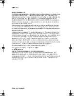
Page 13: ...Safety Information xiii 5055 01x...
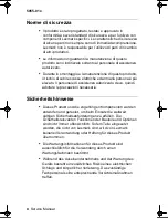
Page 14: ...xiv Service Manual 5055 01x...
Page 50: ...1 36 Service Manual 5055 01x...
Page 185: ...Repair Information 4 31 5055 01x 3 Loosen the thumbscrews as shown...
Page 238: ...4 84 Service Manual 5055 01x...
Page 239: ...Locations 5 1 5055 01x 5 Locations Covers Diagram...
Page 240: ...5 2 Service Manual 5055 01x Major Parts Diagram...
Page 242: ...5 4 Service Manual 5055 01x Printer Controller Board...
Page 243: ...Locations 5 5 5055 01x Printhead Controller Board...
Page 244: ...5 6 Service Manual 5055 01x RIP Board...
Page 245: ...Locations 5 7 5055 01x Power Source Unit 1 Board Power Source Unit 2 Board...
Page 246: ...5 8 Service Manual 5055 01x High Voltage Power Supply Board...
Page 247: ...Locations 5 9 5055 01x Sensor Board Expansion Paper Feeder Controller Board...
Page 248: ...5 10 Service Manual 5055 01x Duplex Unit Controller Board Motor Drive Board Size Sensor Board...
Page 249: ...Locations 5 11 5055 01x High Capacity Paper Feed HCPF...
Page 250: ...5 12 Service Manual 5055 01x High Capacity Paper Feed Configuration...
Page 251: ...Locations 5 13 5055 01x Electrical Parts Layout...
Page 252: ...5 14 Service Manual 5055 01x Driving Parts Layout...
Page 253: ...Locations 5 15 5055 01x Sensor and Switch Locations...
Page 254: ...5 16 Service Manual 5055 01x...
Page 255: ...Locations 5 17 5055 01x Component Locations...
Page 260: ...7 2 Service Manual 5055 01x Assembly 1 Covers 1...
Page 262: ...7 4 Service Manual 5055 01x Assembly 2 Covers 2...
Page 264: ...7 6 Service Manual 5055 01x Assembly 3 Covers 3...
Page 266: ...7 8 Service Manual 5055 01x Assembly 4 Covers 4...
Page 268: ...7 10 Service Manual 5055 01x Assembly 5 Covers 5...
Page 270: ...7 12 Service Manual 5055 01x Assembly 6 Upper Unit...
Page 272: ...7 14 Service Manual 5055 01x Assembly 6 Upper Unit Continued...
Page 274: ...7 16 Service Manual 5055 01x Assembly 7 Base 1...
Page 276: ...7 18 Service Manual 5055 01x Assembly 7 Base 1 Continued...
Page 278: ...7 20 Service Manual 5055 01x Assembly 8 Base 2...
Page 280: ...7 22 Service Manual 5055 01x Assembly 9 Base 3...
Page 282: ...7 24 Service Manual 5055 01x Assembly 10 Electrical...
Page 284: ...7 26 Service Manual 5055 01x Assembly 10 Electrical Continued...
Page 286: ...7 28 Service Manual 5055 01x Assembly 11 I F Controller...
Page 288: ...7 30 Service Manual 5055 01x Assembly 11 I F Controller Continued...
Page 290: ...7 32 Service Manual 5055 01x Assembly 12 Fuser Unit...
Page 292: ...7 34 Service Manual 5055 01x Assembly 13 Cassette...
Page 294: ...7 36 Service Manual 5055 01x Assembly 14 Expansion Feeder 1...
Page 296: ...7 38 Service Manual 5055 01x Assembly 15 Expansion Feeder 2...
Page 298: ...7 40 Service Manual 5055 01x Assembly 16 Duplex Unit 1...
Page 300: ...7 42 Service Manual 5055 01x Assembly 17 Duplex Unit 2...
Page 302: ...7 44 Service Manual 5055 01x Assembly 18 High Capacity Paper Feed 1...
Page 304: ...7 46 Service Manual 5055 01x Assembly 19 High Capacity Paper Feed 2...
Page 306: ...7 48 Service Manual 5055 01x Assembly 20 High Capacity Paper Feed 3...
Page 308: ...7 50 Service Manual 5055 01x Assembly 21 High Capacity Paper Feed 4...
Page 310: ...7 52 Service Manual 5055 01x Assembly 22 High Capacity Paper Feed 5...
Page 312: ...7 54 Service Manual 5055 01x Assembly 23 High Capacity Paper Feed 6...
Page 314: ...7 56 Service Manual 5055 01x...
Page 324: ...I 10 Service Manual 5055 01x...


